# Welcome to {How To}

Configuring and Optimizing OutdoorRouters

## Overview

OutdoorRouter provides cellular SIM card routers and outdoor WiFi extenders to add high-speed 4G/5G connectivity into homes, offices, vehicles, machinery, infrastructure, and more. Using embedded firmware within industrial-grade hardware, they harness the mobility and growing coverage of cellular and WiFi networking.

Unlocking the full capabilities requires properly configuring the router's options to match your use case. Settings like selecting the correct modem, tuning radio access technology powers, choosing frequency bands, activating 5G for networks, and more require understanding of the hardware and software intricacies involved.

The following collection of operation guidance resources offers knowledgeable, practical advice for navigating the firmware interfaces within firmware platforms. Applying these best-practice configuration recommendations allows you to maximize throughput speeds, refine network responsiveness, increase connection reliability, and fully utilize your router.

<figure><img src="/files/A5jN1kKonG1zDDW7kKEi" alt=""><figcaption></figcaption></figure>


# Switch SIM Card

Many of our OutdoorRouter models, including the EZR23(T), EZR33(L/T), and EZR34(T), have dual SIM card slots. By default, the router uses SIM card #1 as the primary card. The two SIM card slots are connected to the same 4G/5G modem. Only one SIM can be active at a time.

## Active SIM Card

### Check SIM Status

To check which SIM card is currently active, go to the "***Device***" section on the right side of the homepage or navigate to "***Network > Mobile***." The interface will indicate whether SIM 1 or SIM 2 is in use.

### Change Active SIM

To change the active SIM card:

1. Go to "***Network > Mobile***" and select "***Edit***."
2. Under the "***General Setup***" tab, choose either "***Primary SIM 1***" or "***Secondary SIM 2***" from the "Active SIM Card" drop-down menu.
3. Click "***Save & Apply***" at the bottom of the page to confirm the change.

The router will switch to using the newly selected SIM card. No need to reboot the router. It takes a few minutes to redial for mobile connection through the new SIM card.

<div align="left"><figure><img src="/files/sQx7RTFJneSC2axxJaUV" alt="" width="375"><figcaption><p>Active SIM and Auto Switch SIM Cards</p></figcaption></figure></div>

***

## Auto Switch SIM

If you are in an area with uneven cell signal coverage and need reliable internet, use the secondary SIM slot to insert a SIM card from another carrier. Go to "***Network > Mobile: Edit***" and enable the "***Auto Switch SIM Card***" function.

When enabled, the [***Mobile-Watchdog***](/mobile/mobile-watchdog) will continuously check the active SIM's internet status. If the watchdog detects the active SIM is offline, the router will automatically switch to the secondary SIM for failover connectivity. This ensures the router maintains internet access even if a carrier's intermittent signal.

The auto-switch function provides seamless cellular connectivity failover using dual SIMs from different carriers.


# Mobile Watchdog

\[Exclusive] Mobile internet guardian program and automatically keep mobile modem alive.

When the 4G/5G routers connect to mobile internet via a SIM card and a mobile broadband modem, the internet connection can sometimes fail or get stuck. The exclusive "**Mobile (WAN) Watchdog**" program is designed to monitor the internet connection to improve reliability continuously.

This **Mobile Watchdog** works by periodically pinging a public DNS server like 8.8.8.8. As long as the ping succeeds, the script does nothing. But if the ping fails after multiple retries, indicating the mobile connection has dropped, the script will automatically reset and reconnect the mobile modem.

Once the modem disconnects and reconnects, it will automatically re-establish a new mobile broadband connection, acquiring a new IP address from the cell network.

This automated monitoring and resetting keeps the mobile internet connection alive even if it hangs or drops for some reason. Implementing a simple script like this provides robust and reliable internet uptime on 4G/5G routers with a mobile broadband modem.

The **Mobile Watchdog** program can be configured through the web interface under "Services > WAN Watchdog." Below is a screenshot showing its configuration options:

<figure><img src="/files/Xh1iUHowG9HgEg9TwxY8" alt=""><figcaption><p>Services > WAN Watchdog: Mobile Watchdog</p></figcaption></figure>

The **Mobile Watchdog** can easily be tuned for reliability against different mobile networks and troubleshooting connectivity issues. The on-demand configuration reload makes adjusting settings simple during testing or changes to the mobile infrastructure.

## **Restart Modem**

The mobile watchdog has default settings to monitor connectivity by pinging a public IP address and restarting the mobile modem when ping failures are detected.

### **Enable / Disable**

The watchdog can be enabled or disabled here. Turn the mobile watchdog script on or off completely. It is enabled by default.

### **Ping IP**

Some mobile carriers may block continuous pings to specific hosts, so if the default ping target stops working, you can change it to alternate public DNS or IP addresses that are more reliable on the given mobile network.

**Save & Apply**\
Remember to click "Save & Apply" to make them active after changing settings. The watchdog script will immediately start using the new configuration without rebooting the router.&#x20;

<figure><img src="/files/xmzXdJqtdrTfDXx7jbp8" alt=""><figcaption></figcaption></figure>

## Reboot Mode

In addition to monitoring connectivity and resetting the modem, the watchdog can be configured to periodically reboot the entire router if the mobile connection remains down for a specified period.

This Periodic Reboot setting provides additional automation to recover from network issues. If a modem reset does not restore connectivity, rebooting the router hardware entirely may fix problems caused by software hangs or resource starvation.

The Reboot Mode settings allow customizing the router recovery behavior when connectivity is lost:

### Diagnosis Times

This specifies the number of failed monitoring cycles before the router is rebooted. The watchdog pings the target IP 8 times per cycle. So if this is set to 5, the router will reboot after 5 cycles of 8 failed pings occur in a row.

### Reboot Times

This sets the maximum number of reboots to attempt. Even if connectivity has not recovered, the watchdog will stop rebooting the router after this many attempts to avoid an endless loop.

### Reboot Counts

This shows the number of router reboots triggered by the watchdog so far. It is a running count that increments each time connectivity loss causes a reboot to be triggered based on the Diagnosis Times setting.

These provide more advanced control to determine when an issue has persisted too long and requires a router reboot instead of just recycling the modem interface. The Reboot Times count prevents endless rebooting if the connectivity failure cannot be restored. The current Reboot Counts indicate how many watchdog-triggered restarts have occurred on the router.

## DEV

After opening the watchdog file, we can change the advanced operation and intervals.

```html
mobile_watchdog() {
        device=$(uci -q get network.$intf.device)
        interface=$(uci -q get watchdog.global.intf)
        failure_loss=5
        failure_loss_reset=10
        linkup=0
        failure_interval=2
        recovery_interval=10
        usbreset_interval=20
        interval=10
        sleep_time=$interval
```

### Operation Process

When the Mobile modem has an internet connection, the Watchdog pins in every 10 seconds. After the first Ping failure, the frequency of pinging changes to once every 2 seconds. If there are 5 consecutive failures, it will trigger a reconnect action for the MOBILE connection using 'ifup.' If there are 5 consecutive failures again, it will perform a mobile modem reset.

* **failure\_loss=5** - The threshold for unsuccessful pings, defaulting to taking the 'ifup' action after '5' consecutive failures.
* **failure\_loss\_reset=10** - The threshold for unsuccessful pings, defaulting to resetting the Mobile Modem after '10' consecutive failures.
* **failure\_interval=2** - The interval for initiating another ping after a previous failure, defaulting to '2' seconds.
* **recovery\_interval=10** - The time interval for initiating another ping after executing the 'ifup' action, defaulting to '10' seconds.
* **usbreset\_interval=20** - The time interval for initiating another ping after resetting the Modem, defaulting to '20' seconds.
* **interval=10** - The interval for regular (successful) ping attempts, defaulting to 10 seconds.

### Change Intervals

Under certain circumstances, such as a weak or unstable mobile signal leading to an extended registration and connection time for the mobile modem, it is possible to modify the intervals to the following durations.

```
failure_interval=30 # Ping every 30 seconds after the first Ping has failed.
recovery_interval=60 # Ping after 60 seconds after 'ifup' the modem 
usbreset_interval=120 # Ping after 120 seconds after resetting the modem
interval=60 # Pings in every 60 seconds
```


# Mobile Protocol

Mobile protocol enables session management, authentication, and IP connectivity to transport data over high-speed cellular networks.

## Introduction

Mobile protocol refers to communication technology and networking standards it uses to connect to cellular networks and transport data.&#x20;

The default mobile modem protocol on OutdoorRouter is "**Mobile-Data**." It has integrated the below QMI and PPP protocol and automatically invokes the most adaptable protocols depending on the mobile networks.

<div align="left"><figure><img src="/files/CIrMomDSBZLhgFmb3y59" alt="" width="375"><figcaption></figcaption></figure></div>

### QMI Protocol

QMI, short for Qualcomm MSM Interface, is a fast proprietary modem protocol used in many mobile modems for managing data sessions and enabling better carrier interoperability.

Due to the difference in the modem chipsets, the different mobile modems might use different QMI proxies. For example, Sierra modems use the QMI\_WWAN proxy, and Quectel modems use the GobiNet proxy. These proxies are using the same QMI protocol and provide similar working performance.

The primary difference is that GobiNet uses kernel space, while qmi\_wwan uses user space. In qmi\_wwan, only one process can handle the control port at a given time, while the GobiNet proxy allows multiple processes to access the device concurrently.

### **PPP Protocol**

PPP, short for Point-to-Point, is a traditional data link layer communications protocol. PPP protocol has been widely used and is the most flexible for device interoperability.

Some mobile carriers might not support QMI protocol to connect to their mobile networks. So, we must change the mobile protocol from the default “QMI” protocol to the “4G-PPP” one.

## **Switch Protocol**

**Example - Switch from Mobile Data to PPP**

If your carrier does not support the default Mobile-Data or QMI protocols, follow these steps to change the modem's protocol to Cellular PPP.

1. After logging into the router, go to "***Network > Interface***". \
   Locate the "**Mobile**" interface and click the "***Edit***" button.
2. Select "***Cellular PPP***" in the **Protocol** dropdown.
3. Click the "***Switch Protocol***" button. Then, it jumps to the Mobile configuration page based on the PPP protocol.

<div align="left"><figure><img src="/files/b6LUeMJ2DU8JM84ytxQ7" alt="" width="375"><figcaption></figcaption></figure></div>

Under the "**General Setup**" tab, ensure the Modem device uses "**/dev/ttyUSB2**". \
Choose the "**Active SIM card**" where your SIM card is inserted, and go to the related SIM1/2 tab to configure the settings below.

* **Service Type**\
  Choose "UMTS/GRPS" on the dropdown menu. Choose "CDMA/EV-DO" for American models.
* Enter the APN parameters - APN address, username, and password.
* For Europe/UK, change the "**Dial Number**" to **\*99#** and use the default ***\*99\*\*1#*** otherwise.
* Then click the "Save & Apply" button to submit the changes.

<div align="left"><figure><img src="/files/1PP1WIvbhga0EY7XihWV" alt="" width="375"><figcaption></figcaption></figure></div>

This will reconfigure the modem to leverage the PPP protocol for maximum compatibility with the mobile carrier. The router will leverage PPP for authentication and IP assignment.


# APN Setting

Accurate APN settings are crucial for successfully establishing connectivity on a mobile network.

**APN**, short for Access Point Name, acts as the gateway for the router to access a carrier's cellular data network. The OutdoorRouter firmware can auto-adapt for many major networks. However, some carriers or data plans require entering specific custom APN settings. Please refer to the steps below to change the APN settings on the Mobile interface.

## Change APN

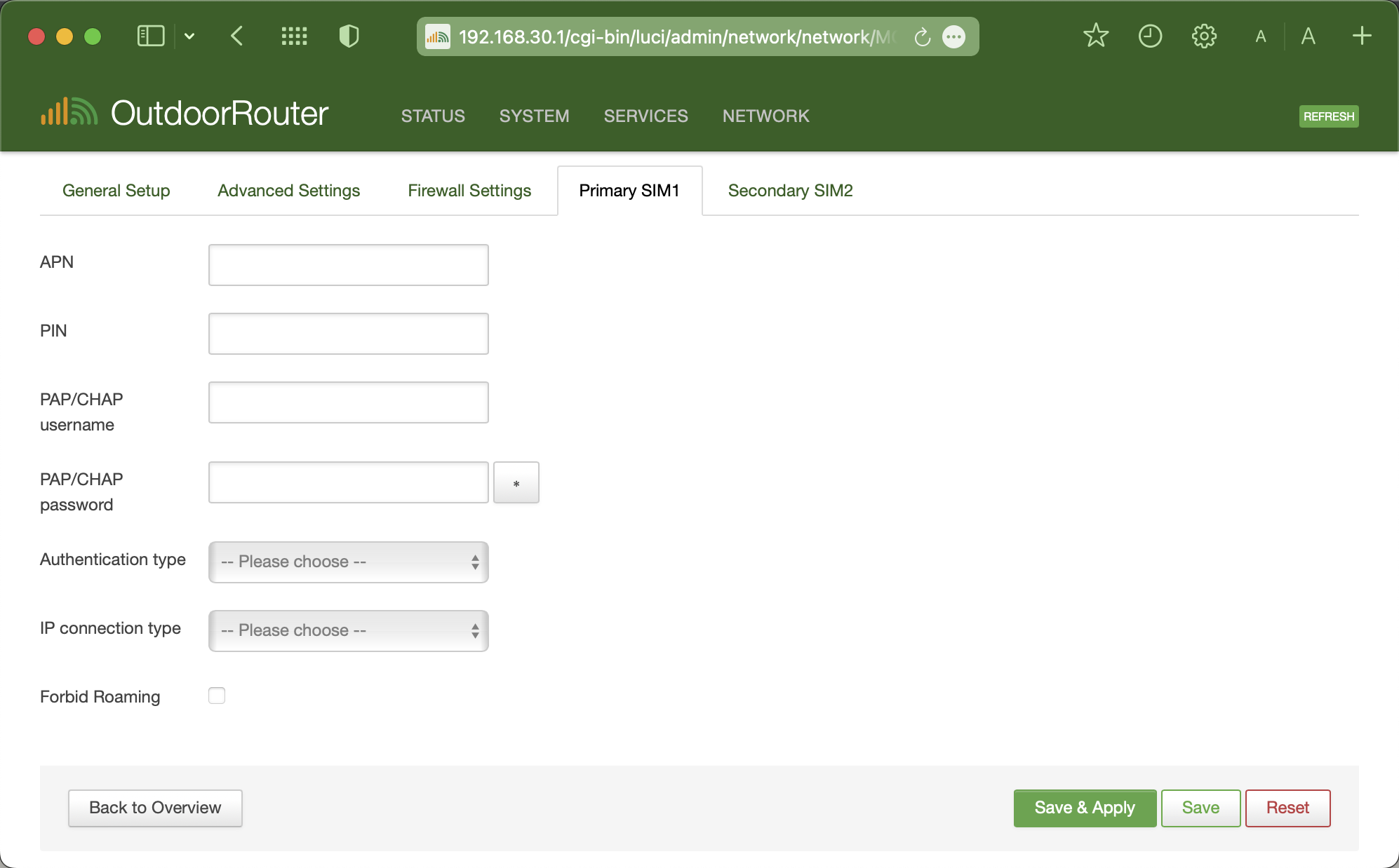
After logging into the router admin, go to "***Network > Interfaces***" and click the "***Edit***" button on the **Mobile** interface.&#x20;

Select the SIM1/SIM2 tabs to set the APNs respectively. The router uses "**Primary SIM1**" on default settings. Refer to the chart below to set APN parameters.

<table data-header-hidden><thead><tr><th width="219">Option</th><th>Value</th></tr></thead><tbody><tr><td>APN</td><td>The APN gateway address</td></tr><tr><td>PIN</td><td>PIN code of SIM card <em>*Usually non-required</em></td></tr><tr><td>Username</td><td>PAP/CHAP Username</td></tr><tr><td>Password</td><td>PAP/CHAP Password</td></tr><tr><td>Authentication type</td><td>Usually use PAP</td></tr><tr><td>IP connection type</td><td>Usually use IPv4 only</td></tr></tbody></table>

<div align="left"><figure><img src="/files/6b3IDvIm7HLyWC6F421c" alt="" width="375"><figcaption></figcaption></figure></div>

Click the "Save & Apply" button on the bottom right corner to apply the new settings. It will jump back to the interface overview page.

The router takes a few seconds to reconnect. We suggest rebooting the router after changing the APN parameters.

## **Generic APN**

The table below provides commonly used APNs for major carriers, which can be used as a reference. However, the exact required APNs can vary across carrier data plans, so always double-check with your provider on the most up-to-date parameters.

<details>

<summary>United Kingdom</summary>

**O2** (23410)

APN: mobile.o2.co.uk\
Authentication: Auto\
Username:  o2web\
Password:  password

**Vodafone** (23415)

APN: internet (or) wap.vodafone.co.uk\
Authentication: Auto\
Username:  wap\
Password:  wap

**Three** (23420)

APN: three.co.uk\
Authentication: Auto\
Username:  \<Leave it blank>\
Password:  \<Leave it blank>

**EE** (23430)

APN: everywhere\
Authentication: Auto\
Username:  eesecure\
Password:  secure

**Tesco** (23410)

APN: prepay.tesco-mobile.com\
Authentication: Auto\
Username:  tescowap\
Password:  password

**GiffGaff** (23410)

APN: giffgaff.com\
Authentication: Auto\
Username:  giffgaff\
Password:  password

**Virgin** (23430)

APN: goto.virginmobile.uk\
Authentication: Auto\
Username:  user\
Password:  \<Not Set>

</details>

<details>

<summary>United States</summary>

Here are the internet APN settings for some USA mobile phone operators.

**AT\&T**

APN: broadband\
Authentication: PAP\
Username:  \<leave in blank>\
Password:  \<leave in blank>

**T-Mobile**

APN: fast.t-mobile.com\
Authentication: PAP\
Username: \<leave in blank>\
Password: \<leave in blank>

**Sprint**

APN: cinet.spcs\
Authentication: PAP\
Username: \<leave in blank>\
Password: \<leave in blank>

**Verizon**

APN: vzwinternet\
Authentication: PAP\
Username:  \<leave in blank>\
Password:  \<leave in blank>

**Visible**

APN: vsbinternet\
Authentication: \<leave in blank>\
Username:  \<leave in blank>\
Password:  \<leave in blank>

**Twilio**

APN: wireless.twilio.com\
Authentication: PAP\
Username:  \<leave in blank>\
Password:  \<leave in blank>

**Ting X3**

APN: wireless.dish.com (or tethering.dish.com)\
Authentication: PAP\
Username:  \<leave in blank>\
Password:  \<leave in blank>

**Ting X1**

APN: wholesale\
Authentication: PAP\
Username:  \<leave in blank>\
Password:  \<leave in blank>

</details>

<details>

<summary>Australia</summary>

Here are the internet APN settings for some Australian mobile phone operators.

**Telstra**

APN: telstra.internet\
Authentication type: PAP\
Username: \<Leave in Blank>\
Password: \<Leave in Blank>

**Vodafone**

APN: live.vodafone.com\
Authentication type: PAP\
Username: \<Leave in Blank>\
Password: \<Leave in Blank>

**Optus**\
*Note: Please use the Optus SIM card with the Broadband plan. Optus prevents a mobile plan SIM card from being used on a router.*

APN: connect\
Authentication: PAP\
Username:  \<Leave in Blank>\
Password:  \<Leave in Blank>

</details>


# Mode & Band Locking

Locking 4G/5G Router's Modes and Bands

While our 4G/5G routers automatically leverage available mobile networks on the default settings, selectively locking bands and modes is an alternative for some environments. Customizable low-level modem parameters empower tuning connectivity to unique scenarios similar to carrier-class gateways.

Our intuitive web UI simplifies modem configuration on all router models. One-click locking instantly unleashes the potential without coding work being necessary. It matches the router precisely to deployment needs, such as high-density urban performance, maximum rural reach, failover resilience, and everything in between.

## Modem Modes and Bands

The modem modes refer to the different generations of cellular network technologies, such as 3G, 4G, and 5G. A modem is typically designed to operate on the most advanced network mode available while also providing backward compatibility to support lower-generation modes. These modem modes correspond to the "Access Tech" displayed on the router's front page.

The mobile modem can operate on various frequency bands for each network mode. Different band numbers represent the specific bands supported.<br>

<table><thead><tr><th width="149">Mode</th><th width="154">Band Name</th><th>Network Technology</th></tr></thead><tbody><tr><td>3G</td><td>utran</td><td>UMTS, WCDMA, CDMA2000</td></tr><tr><td>4G</td><td>eutran</td><td>LTE, LTE-A, WiMAX, HSPA+</td></tr><tr><td>5G</td><td>ngran</td><td>5GNR (5G New Radio), 5G-NR mmWave</td></tr></tbody></table>

### **Access Tech**

After accessing the router admin, we can find the "Access Tech" on the front page under the modem section. You can refer to the above chart to find the network mode it connects to.

### **Mobile Interface**

Navigate to "Network > Interfaces > Mobile: Edit > Tab of Advanced Settings" to check the router's mode and band settings.

**Any** - Means use any available modes or bands.\
**Highlight** - Light grey background. This means selected and activated settings.

**Supported Modes** - List the modes supported by the mobile modem.\
**Preferred Mode** - The selected mode will preferentially connect to.

**Supported Bands** - List the frequency bands supported by the mobile modem. \
utran is 3G, eutran is 4G, and ngran is 5G.&#x20;

<mark style="color:orange;">Before trying to lock the modes or bands, please check the guidance below. If you operate the modem incorrectly, it will malfunction.</mark>

<div align="left"><figure><img src="/files/Ax7oWtYZGShD8y4FwXBZ" alt="" width="375"><figcaption><p>Example of 5G-NR Modem Router's Mobile Interface</p></figcaption></figure></div>

***

## Mode Locking

In most cases, there is no need to modify the default modem mode settings. A typical optimization is to exclude slower network modes, such as 3G. Additionally, the modem can be configured to operate on a single mode by setting both the supported and preferred modes to the same option.

### 5G Only

It is not recommended to use the 5G-only mode. Most 5G networks currently operate in 5G-NSA (Non-Standalone) mode, which means they rely on the existing 4G-LTE network infrastructure. Disabling the 4G mode will prevent the device from connecting to any network.

When a 5G modem connects to a 5G-NR network, it still utilizes 4G-LTE network bands to carry a significant portion of the bandwidth. You can use the [AT+QCAINFO](/dev/command/at-5g/qcainfo) and [AT+QENG](/dev/command/at-5g/qeng) commands to check the specific bands the modem is connected to. If the serving cell tower supports multiple 5G-SA (Standalone) bands, you may try the 5G-Only mode.

### 4G Only

As 5G network coverage is still in the deployment and expansion phase, the 5G cellular signals can be weak or unstable in many areas, particularly in remote or rural locations. Whenever the modem transitions from a 4G or lower network to a 5G network, the mobile device will need to reconnect, which can cause interruptions.&#x20;

To prevent such connection disruptions, the modem can temporarily be set to 4G-Only by selecting both the supported and preferred modes as 4G, as illustrated in the image below.

<div align="left"><figure><img src="/files/SIEFzVGdkr0Joedi75Ya" alt="" width="375"><figcaption><p>4G-Only Mode Locking</p></figcaption></figure></div>

***

## Band Locking

Before locking the modem's bands, we must collect the frequency bands supported by your mobile carrier and the serving cell towers. Locking to non-supported or unavailable bands will cause malfunction.

You can use the [AT+QCAINFO](/dev/command/at-5g/qcainfo) and [AT+QENG](/dev/command/at-5g/qeng) commands to check the specific bands the cell towers broadcast.&#x20;

**RAN** – Short for Radio Access Network.

**\[3G] UTRAN** means UMTS Terrestrial RAN. All the Utran bands are the 3G network bands.\
**\[4G] E-UTRAN** means Evolved UTRAN. All the E-Utran bands are 4G LTE-based bands.\
**\[5G] NG-RAN** means Next Generation RAN. These are the 5G New Radio bands.

After choosing your preferred modes or bands, click the “Save & Apply” button in the bottom right corner. The router will save the updated settings, automatically redirect back to the interface overview page, and reinitialize the mobile connection using the freshly selected options.

If the settings are inefficient, perform a full power cycle by unplugging and reconnecting the power supply. It will clear cached holdovers from old configurations and compel the router to use the current defined settings.


# Modem Diagnosis

Validate mobile connectivity and determine if SIM card, signals, APN settings troubleshooting needed.

Here are the systematic troubleshooting procedures for diagnosing mobile internet connectivity.

This article will be updated periodically to reflect the latest cellular technology and firmware upgrades. The troubleshooting steps provided will correspond to the most current firmware version.

## Verify Status

To verify the mobile internet connectivity, access the router and check the mobile status.

Firstly, power up the router by connecting the power adapter. Wait 3-5 minutes to fully start up. Connect to the WiFi hotspot or use a LAN cable to connect directly to the router. Type the router's IP address in the browser address bar to access the admin panel.

Then, check the below pages for the mobile connection status.

* **Front Page: Device**\
  Check the "Active SIM Slot" and "SIM Status" on the "Device" section of the front status page.
* **Network > Interface**\
  Locate the "Mobile" interface and check the Rx/Tx data stream and IPv4 address.

> **If the Device status is "Connected"** and Mobile obtained an IPv4 address, \
> go to the **"Network > Diagnostics"** section and use the **Ping** tool to ping a popular website or public IP address, like 8.8.8.8, to test basic internet connectivity.&#x20;
>
> If ping tests fail and the router cannot reach public internet, continue the below troubleshooting steps.

> **If the Device status is "Not Connected"** and there is no IPv4 on the Mobile interface, \
> the router is not obtaining mobile data connectivity correctly.&#x20;
>
> Then, continue with the next troubleshooting steps.

***

## Troubleshooting

Several common factors usually cause SIM card routers to fail to connect to the mobile network. Follow the below troubleshooting guide to rule out potential issues.

### Signal Quality

Check the signal quality in the area where the router is installed. The mobile modem requires at least **-101 dBm to -105 dBm** to access the mobile data network. \
*Note: The signal sensitivity can differ depending on different modem models.*

* **Check on Router**\
  After logging into the router, check the **"RSRP"** value on the **"Device"** section of the front page.\
  *Note: Depending on the carrier policy, it may not show signal strength when the SIM is unregistered.*<br>
* **Check on Phone**\
  Use a smartphone with the same carrier SIM and check the mobile signal bars and network type. -101 dBm is about 2 bars on a smartphone.&#x20;
* **Signal Test Tutorial**

  To accurately validate mobile signal strength, refer to this **🔗**[**Signal Test Tutorial**](https://www.outdoorrouter.com/field-test-4g-mobile-signal-strength/), and use a signal testing APP or enter field test mode to check the RSRP value.

> If the mobile network is **4G**-LTE or **5G**-NR and the mobile signal is more than **2 bars** (or RSRP value is stronger than **-101 dBm**), continue to the next step to verify SIM card and APN settings.

> If receiving 2G or 3G network, or the signal strength is lower than -101 dBm RSRP or fewer than 2 signal bars, insufficient mobile signal could be the cause of connectivity problems.
>
> First, try relocating the router closer to a window or an open space with fewer barriers, especially without metal roof, on a higher point on the pole, and away from other RF antennas and high voltage electrical wires. Then, retest the signal measurements to check if signal has increased.
>
> > If still does not resolve poor signal issues, consider upgrading the mobile antennas with a high-gain [outdoor external antennas](https://www.outdoorrouter.com/product-category/outdoor-router-accessory/4g-antenna/), which can help concentrate distant mobile signals.

### **SIM Card**

* Verify the SIM card is properly **activated** and has an active plan with sufficient data allowance. *Note: Many issues stem from inactive SIM cards or reaching monthly data limits.*
* Make sure the SIM card is inserted into the **SIM1 slot** or whichever slot is set as the "Active SIM" in the Mobile settings. By default, the router uses the primary SIM card in the SIM1 slot.
* Only insert or swap SIM cards while the router is **powered off**. \
  If you insert a SIM with the router on, reboot the router to detect the SIM card properly.
* Inspect the SIM card for damage or scratches on the golden contact pins. \
  A damaged SIM can cause intermittent connectivity problems.
* **PIN Code** - If a custom PIN is set for your SIM, enter this exact PIN string on the Mobile interface. If the SIM has no PIN enabled or has a default PIN, leave the PIN field blank.
* **Unlimited Data Plan** - If your SIM card has an unlimited data plan, please verify with your provider whether the plan allows use in a SIM router for shared connections. Many unlimited plans restrict usage solely to mobile devices like phones and tablets. If your unlimited plan does not permit router use, please consider upgrading to one that supports SIM router connectivity.
* **Bound SIM Card** - If your SIM card was provided with a carrier-branded mobile modem, it may be locked to only work with that specific device, even if a different manufacturer makes the modem. Such a SIM likely cannot be used in a third-party router. In this situation, contact your SIM provider to try to unlock the SIM card. If it cannot be unlocked, please obtain a compatible SIM card and data plan to use with your router.

### APN Setting

Configuring proper APN (Access Point Name) settings is vital for the router to authenticate and connect to the carrier mobile network. While the router firmware attempts to auto-configure these parameters for major providers, some carriers may require entering customized APN profiles.

First, verify the APN details by consulting your mobile network operator. Ask them for the complete APN credentials, including APN address, username, password, and authorization type.

Then, refer to the [**APN Setting Tutorial**](/mobile/apn) to set up APN parameters. After setting APN, it takes a few seconds to redial. Suggest rebooting the router to ensure the new settings take effect.

### Mobile Protocol

The default mobile modem protocol is "Mobile-Data," which automatically selects the most suitable protocols based on the mobile network. The default protocols may not be supported in rural areas with limited cell tower availability or when using some Virtual Network Operators' (VNO) SIM cards. Refer to the [**Mobile Protocol Tutorial**](/mobile/protocol) to change to the traditional PPP protocol.

### Hard Reboot

If the Mobile interface persists with an error like “Modem Device Not Present," the internal mobile modem might fail to initialize correctly. It often stems from an interruption when first attempting to register the SIM card on boot up. It can also indicate a hardware defect.&#x20;

Please try a hard reboot by unplugging the power adapter and leaving it down for 60 seconds before replugging it. It forces a fresh modem initialization sequence and new network registration rather than relying on cached data.

### Revert Settings

If the mobile internet worked properly previously but suddenly stopped working after modifying configurations, the new settings most likely have interference issues.&#x20;

First, methodically revert any new adjustments made before the connection dropout. After rolling back recent changes, reboot the router to reinitialize all services with the confirmed working configuration.&#x20;

If mobile connectivity fails to restore and reverting alone cannot revert problems, perform a factory reset to wipe all customizations and restart from default factory settings.

***

## Further Debugging <a href="#debug" id="debug"></a>

If the troubleshooting steps above do not resolve your mobile connection issue, please gather the information below and email it to us for further debugging:

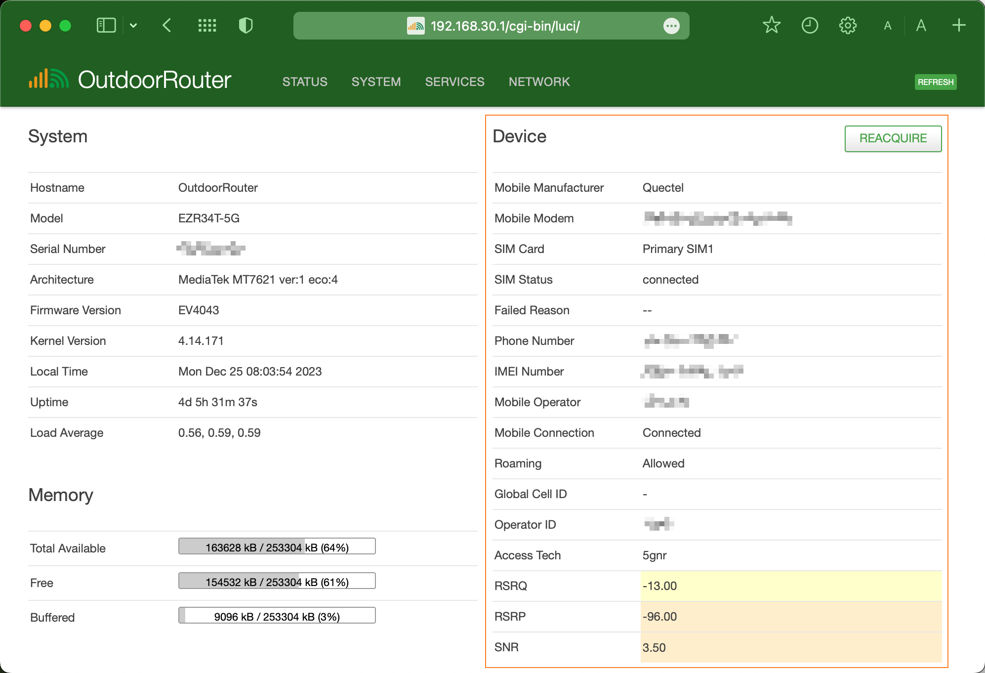
* **Homepage - Device Section**\
  After logging into the router, take a screenshot of the *"Device"* section on the right side of the homepage.
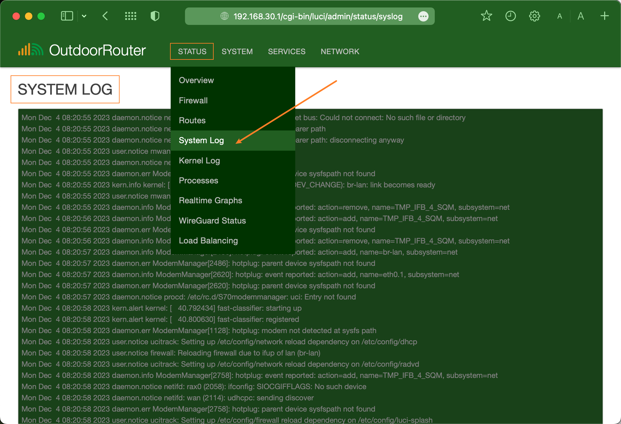
* **Complete System Log**\
  Navigate to *"Status > System Log"* and copy the router's system log (green background section) to a *\*.txt* or *\*.doc* file.
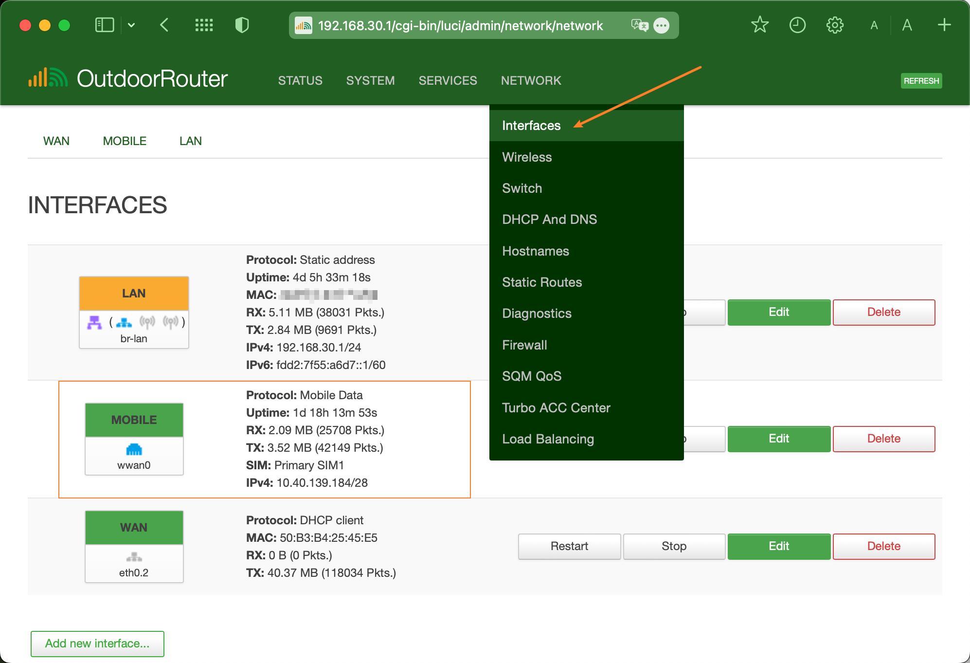
* **Mobile Interface Status**\
  Take a screenshot of the Mobile interface status under *"Network > Interface > Mobile."*

<div><figure><img src="/files/5NS4YR6DILsgGuKTRcdO" alt=""><figcaption><p>Homepage: Device Section</p></figcaption></figure> <figure><img src="/files/8U614N9H9zAxFXXajTAE" alt=""><figcaption><p>Status > System Log</p></figcaption></figure> <figure><img src="/files/dkWDiDfwNFgTwz19Yf7d" alt=""><figcaption><p>Network > Interfaces > Mobile</p></figcaption></figure></div>

The above-mentioned information is crucial for troubleshooting mobile connectivity. While the device status and mobile interface provide basic status and error, the timestamped system log is essential for diagnosing connectivity over time.&#x20;

Please include all three information sources when reporting issues. Together, they give a complete picture needed to trace and debug connectivity problems.


# Change TTL Value

With individual control over the IP packet lifespan per interface, you can optimize TTL best to suit the type of connected devices and usage profiles.

TTL determines the maximum router hops allowance before packets expire. Tuning this can optimize connectivity in some specialist scenarios like global roaming networks. The default TTL value (64) suffices for most users.

## What is the TTL?

TTL stands for "Time To Live"; it refers to the maximum number of mobile modem hops/routers a data packet can traverse before being discarded or dropped. TTL ensures packets don't circulate endlessly in routing loops.

The common TTL values used on a mobile modem are 64, 65, or 128.

* The default TTL 64 usually works perfectly for most mobile carrier networks.
* Higher TTL > 128 allows packets to travel further, which can maintain connectivity for international roaming.&#x20;
* Lower TTL < 64 may reduce latency and lag for long routes by forcing shorter paths. However, values below 30 can cause a loss of connectivity.

## Change the TTL Value

Our 4G and 5G routers allow us to change each interface's TTL value individually with a few clicks on the web page. Please follow the steps below to change the mobile modem's TTL value.

1. Go to "Network > Interfaces" after logging into the router.
2. Navigate to the "Mobile" interface and click the "Edit" button.
3. Tap the tab "Firewall Settings".
4. Choose a TTL value from 64, 65, and 128.\
   You can also click "-- Custom --" to input a custom TTL value.
5. Click the "Save & Apply" button on the bottom right corner.
6. Finally, perform a hard reboot by unplugging the power supply, waiting 30 seconds, reconnecting power to reboot the router, and reloading the settings from scratch.

<figure><img src="/files/Q1Nugs22BT9ZS1Q42k7f" alt=""><figcaption></figcaption></figure>


# Detach Reattach

## Redial Request

The OutdoorRouter firmware does not retry the mobile connection when it is already stable. However, the mobile carrier may request the SIM card to detach and reattach from the network in the following situations:

1. **Network Updates**

   The carrier may be pushing network or configuration updates that require detaching connected devices and having them reattach to apply the changes.
2. **Connection Refreshing**

   Periodic detach/reattach requests can help refresh the connection and keep it from going idle or having long-lived inactive sessions.
3. **Resource Balancing**

   By shuffling connections around, the carrier can better balance load across its cellular towers and spectrum resources.
4. **Security and Policy**

   Carriers may mandate periodic re-authentication and reattachment to reinforce security policies and ensure compliance.

The carrier-initiated detach/reattach procedures help maintain optimal network operations and performance, keep connections fresh, resolve issues, and enforce security policies. Forcing this process periodically allows the carrier to improve the experience for end users.

## Example

#### Detach with Reattach

You may find the below log record in the router's system log when the mobile connection drops unexpectedly, even though the mobile signal coverage is steady.

```
[modem0/bearer3] verbose call end reason: [cm] detach-with-reattach-lte-nw-detach
```

**Detach** - refers to the process when a mobile carrier requests to disconnect from the network.\
**Reattach** - indicates an attempt to re-establish a new LTE network connection after detaching.\
**NW** - stands for "network" in this context.&#x20;

This above log entry indicates that the mobile carrier has requested the router's SIM card to detach and reattach from the LTE network, without any manual intervention. This is expected behavior, allowing the carrier to proactively improve the mobile network.


# Fix PLMN Error

PLMN is the core identifier for the mobile network that allows cellular devices like modems to identify and connect to specific carrier networks globally correctly.

## What is PLMN?

PLMN stands for "Public Land Mobile Network," which refers to the core mobile network a cellular modem connects to. The PLMN dictates authentication, subscription eligibility, roaming status, APN access point name, and other cellular connectivity parameters for modems and phones.

Many mobile carriers have multiple PLMNs on different bands/technologies (3G, 4G, 5G) that mobile SIM modem routers must scan for and select the appropriate one.

## PLMN-Not-Allowed

A SIM card used on a mobile modem router must have a valid subscription to register with and be granted access to a mobile network PLMN.  Sometimes, the mobile SIM modem router might be unable to connect to the mobile network and get the "PLMN-Not-Allowed" error on the system log, as shown below.

<pre class="language-html"><code class="lang-html">&#x3C;warn> [modem0] network reject indication received
&#x3C;warn> [modem0] service domain: cs-ps
&#x3C;warn> [modem0] radio interface: lte
&#x3C;warn> [modem0] reject cause: <a data-footnote-ref href="#user-content-fn-1">plmn-not-allowed</a>
&#x3C;warn> [modem0] mcc: xxx
&#x3C;warn> [modem0] mnc: xxx 
</code></pre>

### How to Fix PLMN Error?

The "PLMN not allowed" error usually means an unauthorized or invalid subscription attempt. Some common reasons can also cause PLMN errors. You may follow the steps below to check the potential reasons individually.

1. **Poor Signal Strength:** Weak or unstable signal reception can lead to the "PLMN-not-allowed" error. If the signal quality, especially the RSRP and SNR values is too low or floats in a too large range, it may result in this error. You can relocate the route to another spot with a stronger signal or upgrade to higher-gain mobile antennas to fix this problem.
2. **Network Restrictions:** The mobile SIM card provider may have specific restrictions that prevent the router from connecting to certain PLMNs. This could be due to roaming restrictions, network access policies, or contractual limitations. In this case, you should contact the SIM card provider to waive the restrictions for your SIM card.
3. **SIM Card Configuration:** Issues with the mobile modem protocol, PIN code, and APN settings may lead to the "PLMN-not-allowed" error. You can refer to the [mobile protocol settings](/mobile/protocol) and [mobile APN tutorials](/mobile/apn) to configure them for the router.
4. **Manual PLMN Selection:** If the router is set the router to lock the networks or mobile bands that the mobile provider does not support, it may encounter issues if the preferred PLMN is not available or allowed. In this case, reconfigure the router without band locks and reboot it to fix it.
5. **Firmware or Software Issues:** Outdated firmware or software on the mobile modem router can sometimes cause connectivity issues. Updating the router's firmware may address these issues.
6. **Network Congestion:** In some cases, mobile network congestion or overload can result in the "PLMN-not-allowed" error, especially during peak usage times or in densely populated areas. Please wait a few minutes and try again. You can also upgrade your data plan to priority business or commercial grade to fix it.

[^1]:


# Firewall

The router firewall controls the forward packet streams from incoming network interfaces to outgoing network interfaces.

The firewall functions in a 4G/5G SIM card router, providing a powerful and flexible way to control and secure network traffic. It allows you to tailor the security settings to your specific needs.

* **Zones and Policies**: Organizes network interfaces into zones, such as the LAN (local area network) zone and the WAN (wide area network) zone. Policies define the rules for traffic flowing between these zones.<br>
* **Traffic Filtering**: The firewall allows you to filter traffic based on various criteria, including source and destination IP addresses, ports, protocols (TCP, UDP, ICMP), and more. You can create rules to allow, reject, or drop specific types of traffic.<br>
* **Port Forwarding**: This function enables you to forward incoming traffic on a specific port to a specific device or service on your local network. It's commonly used for services like web servers, game servers, or remote desktop access.<br>
* **Network Address Translation (NAT)**: NAT allows you to share a single public IP address among multiple devices on your local network. It translates the private IP addresses of your local devices to the public IP address when accessing the internet.<br>
* **Packet Marking**: You can mark packets based on specific criteria, such as source or destination IP addresses or ports. This marking can then be used to apply specific routing or Quality of Service (QoS) rules.<br>
* **Logging and Monitoring**: The firewall logging capabilities allow you to monitor and analyze network traffic. This can be useful for troubleshooting or identifying potential security threats.<br>
* **Load Balancing**: The load balancing distributes incoming traffic across multiple WAN & Mobile interfaces to improve performance and redundancy.


# Port Forward

Port forwarding applies *network address translation* (NAT) and redirects a communication request from one address and port number combination. Port Forwarding allows remote computers to connect the outdoor router within a private local-area network (LAN).

## Enable WAN Forward

To configure the port forwarding, log in to the router and go to "Network > Firewall."

* Under the tab of "General Settings," change forward to "Accept."
* In the **Zones** section, change the **Forward** on the WAN row from "Reject" to "Accept."
* Click the **Save & Apply** button on the bottom right corner.

<figure><img src="/files/F8j3DxUStkVyxY2B7cRy" alt=""><figcaption><p>Enable WAN Forward on the Firewall</p></figcaption></figure>

## Public Port Forwards <a href="#public-port-forwards" id="public-port-forwards"></a>

Click the tab "Port Forwards" to enter the configure section on the **New port forward** section:

1. **Name:** Enter the reference name. e.g., *Test*
2. **Protocol:** Select "TCP, UDP, or TCP+UDP."

   *If you don't know the protocol, please choose TCP+UDP. If you know whether it is TCP or UDP, select TCP or UDP. This can effectively reduce resource consumption.*
3. **External Zone:** Select "WAN"
4. **External Port:** Set the port number you want to access from the external network. We suggest selecting the WAN port between 1025\~25534. Do not use the standard ports occupied by other services, *such as 23, 80, 433, 3389, 7700, 10080, etc.*
5. **Internal Zone:** Select "LAN"
6. **Internal IP Address:** Select from the list of connected intranet hosts.
7. **Internal Port:** Enter the port number that needs to be forwarded from the intranet host
8. Click the button "Save & Apply" to execute the new settings.

<figure><img src="/files/CXi5mZo6Ph6vPihaq17s" alt=""><figcaption></figcaption></figure>

*The above example forwards a local host 192.168.30.113:80 to WAN port 1180. Thus, we can access the 80 port on the host of 192.168.30.113 from the public IP address plus port number 1180.*

*The public port forward does not change the accessing port in the local networks.*

**NAT Loopback** is turned on after saving a new port forward rule. It allows the intranet terminal to access the local hosts using the public IP address of the routed external network interface. To reduce the consumption of router resources, you can click the **"Edit"** button on the saved port forward rule list to disable it.

{% hint style="info" %}
Public port forwarding relies on a public IP address, which most 4G/5G SIM card internet connections require. Please get the public IP from the 4G carrier to activate the public port forwarding.

Except for a public 4G IP address, you can also try forwarding it to an OpenVPN or WireGuard server through the VPN tunnel.
{% endhint %}

## Intranet Forwards <a href="#intranet-forwards" id="intranet-forwards"></a>

To access another host from the local network, we can set up intranet forwarding based on IPtables and the firewall settings.

Go to "Network > Firewall," and click on the tab "Custom Rules." Add the new iptable rules. Below are the example codes to forward 192.168.30.113:80 to router IP 192.168.30.1:1180.

`iptables -t nat -A PREROUTING -d 192.168.30.1 -p tcp --dport 1180 -j DNAT --to-destination 192.168.30.113:80 iptables -t nat -A POSTROUTING -d 192.168.30.113 -p tcp --dport 80 -j SNAT --to 192.168.30.1`

<figure><img src="/files/TdEAZlISWe0ohLnyp88C" alt=""><figcaption></figcaption></figure>

## Open New Port <a href="#open-new-port" id="open-new-port"></a>

After accessing the router, go to "Network > Firewall > Traffic Rules: Open port on router" to add a new port on the 4G router.

* **Name:** Input name of the new port
* **Protocol:** Choose from TCP or UDP
* **External port:** The new port number

After entering the above parameters, click the "Add" button. Then click the "Save & Apply" button in the bottom right corner. The new port will appear on the "Traffic Rules" list.


# WiFi Hotspot


# WiFi Relay

A WiFi relay, also known as a WiFi repeater or WiFi extender, is a feature that allows a router to connect to an existing WiFi network and rebroadcast the signal to extend the coverage range.

The OutdoorRouter can be configured in WiFi client mode to connect to an existing WiFi hotspot as a client device. When joining another WiFi network, the router will obtain internet connectivity through that target wireless access point.

The WiFi relay function requires connecting to a single-band, single-channel WiFi network, and a mixed 2.4/5.8G hotspot is not supported.

When the OutdoorRouter has both 2.4GHz and 5GHz WiFi hotspots. Each WiFi frequency band can be configured as a separate WiFi relay.

## Step-by-step

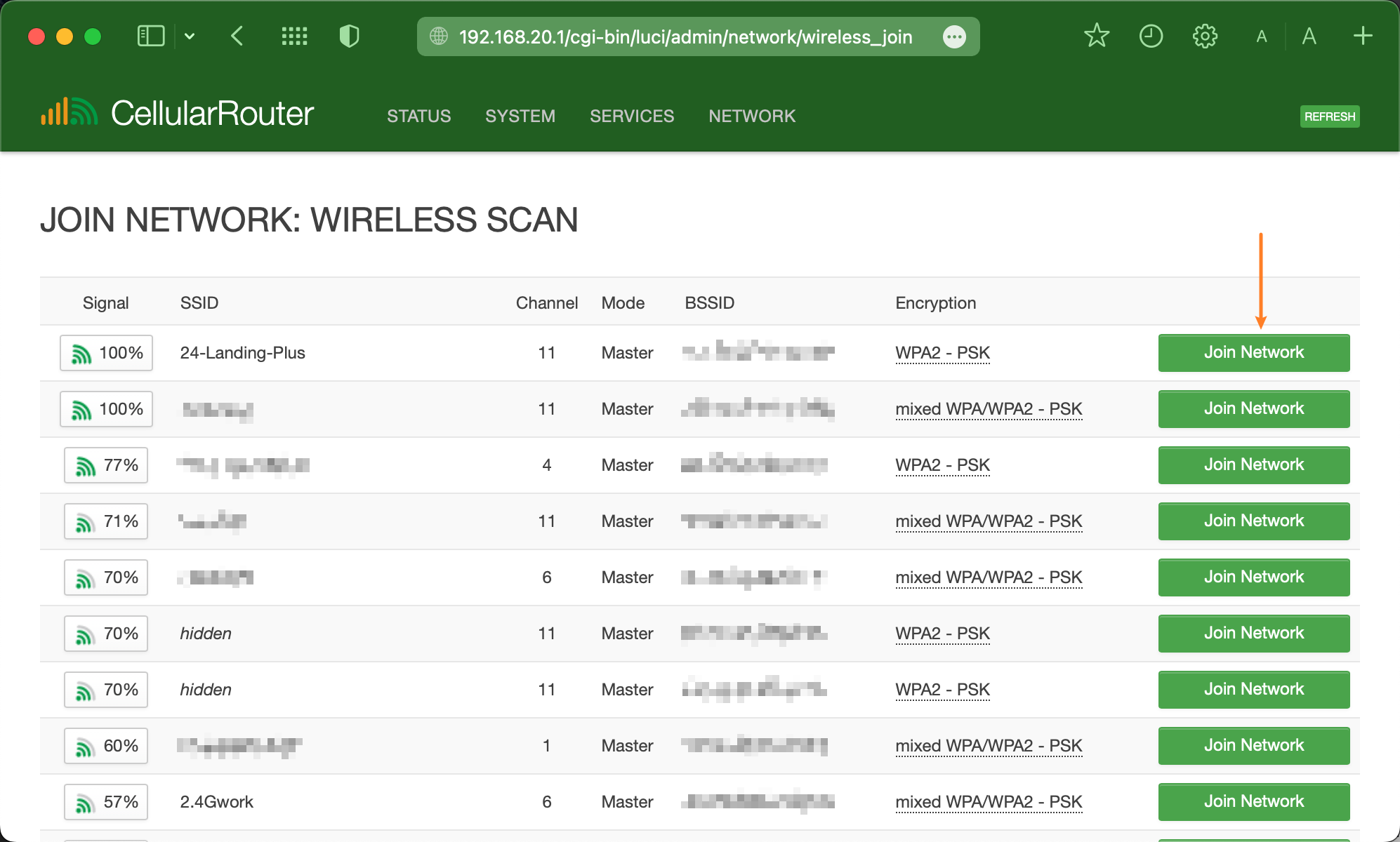
To set up the router as a WiFi relay client, log into the router and go to "**Network > Wireless**."\
Click the "**Scan**" button and wait a few seconds for the scanning result.\
Select the target upstream WiFi network, and click the "**Join Network**" button.

<div><figure><img src="/files/QcUJ2OnbL2AYYnagM07W" alt=""><figcaption><p>Scan for WiFi Relay Client Connection</p></figcaption></figure> <figure><img src="/files/dtISgYL5vu0G31OSBLBO" alt=""><figcaption><p>Join Network of Target Upstream WiFi Network</p></figcaption></figure></div>

After clicking the "Join Network" button, it jumps to step #1 of the WiFi relay configuration page.\
Enter the full WiFi password for the upstream network in the "**WPA passphrase**" field.\
Leave all other settings unchanged.

* **Replace wireless configuration** - Leave it unchecked. Check this to clear existing WiFi settings from the radio interface.
* **WPA passphrase** - Enter the password of the upstream network here.
* **Name of the new network** — Leave" wwan" as the default. When connecting more than one WiFi relay, use a different network name for the new WiFi relay link.
* **Create/Assign firewall zone -** Leave it as "wan + Mobile" to deploy the prebuilt firewall rules.

Then, click the "**Submit**" button to save settings and move to the next step.\
You can review and check the target WiFi hotspot information, then scroll down to the bottom and click the "**Save & Apply**" button.

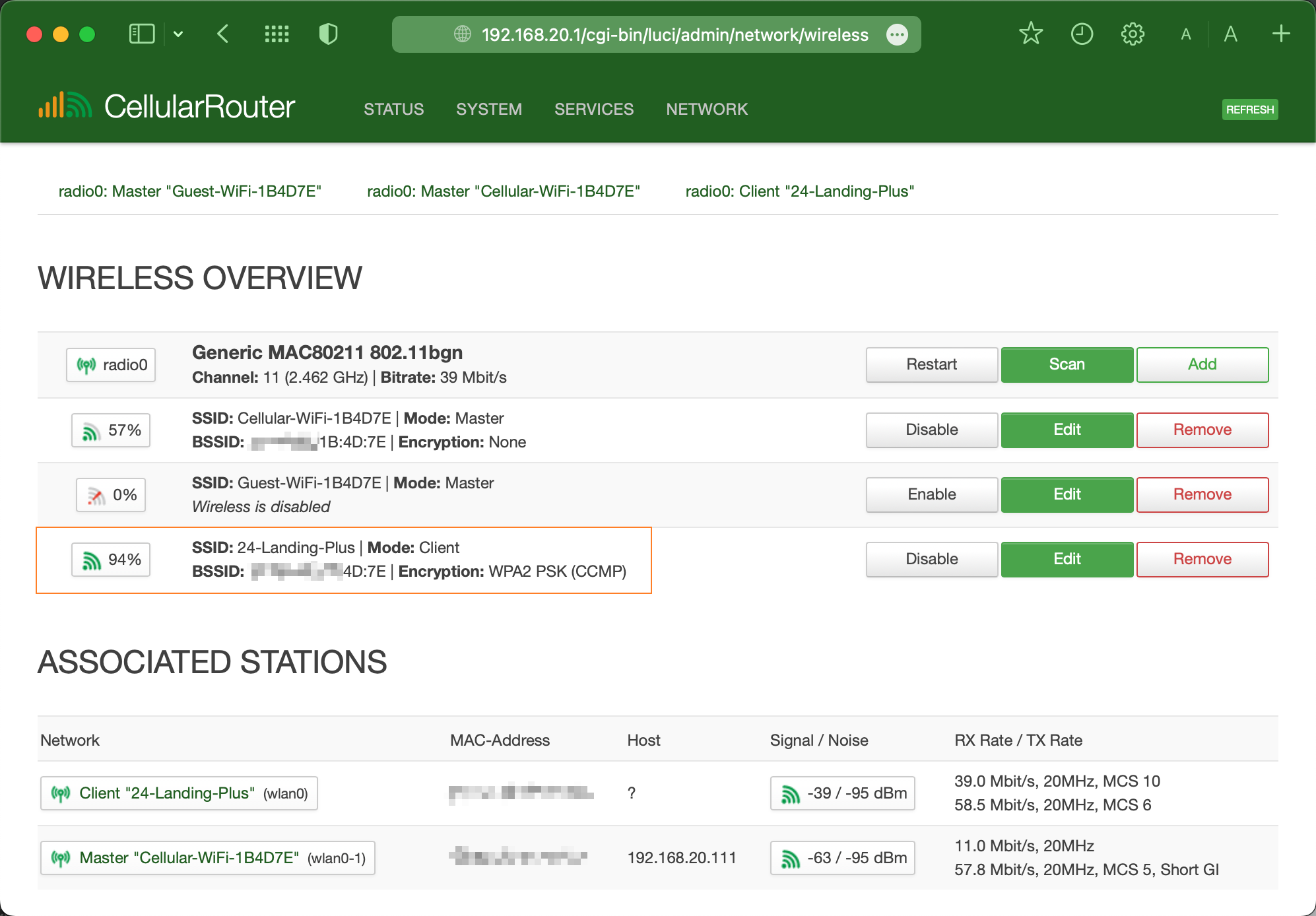
After successfully joining a WiFi network, as the image below shows, with a "***Mode: Client***," the router has successfully joined the defined network and authenticated. Traffic will flow from the upstream WiFi network through the router and be used by devices connected to the router's LAN and master WiFi hotspots.

<div align="left"><figure><img src="/files/sgH09OjZyqHW4fc4qDA1" alt="" width="375"><figcaption><p>Wireless Overview Page with WiFi Relay Client Mode</p></figcaption></figure></div>

{% hint style="warning" %}
Do not modify the default Operating Mode, Channel, or Bandwidth settings under Interface Configuration when joining a WiFi network for relaying. Keeping the defaults allows automatic matching of the upstream network's settings, which is required to associate as a client device successfully.

To prevent IP conflicts, ensure the router's LAN subnet differs from the upstream WiFi network's subnet. For example, set the router's LAN IP to 192.168.20.1 if the upstream network uses 192.168.1.x.
{% endhint %}

***

## Debugging

**Delete Before Retry**

If the WiFi relay configuration does not successfully connect and bridge traffic from the upstream network, click the "Delete" button on that specific Client SSID entry to remove the incomplete relay configuration. Repeating the relay setup process from scratch can clear invalid settings if the router had issues associating as a wireless client on the first pass. Ensure accurate WiFi password entry and compatible settings to allow proper joining as a client station device.

**WiFi Channel & Reconnection**

Before setting up the WiFi relay, we suggest setting custom WiFi bands on the target upstream router. When the upstream WiFi band is on auto mode and has changed after rebooting, the WiFi relay will be unable to reconnect.


# Guest WiFi

Enabling a guest WiFi hotspot to provide internet access to guests and add a security layer by keeping guest devices separate from the master network.

## What is Guest WiFi

A guest WiFi hotspot can provide visitors or guests with internet access without compromising the main network's security. The guest WiFi runs on a separate subnet isolated from your primary network.

The EZR3X routers are prebuilt Guest WiFi and related interfaces and firewall zones. Below is the tutorial for setting Guest WiFi on EZR4X series routers, including EZR24 and EZR34(T).&#x20;

***

## Auto Script Configuration

The auto script tutorial is to automatically create Guest WiFi hotspots and interfaces without too many operations on the web UI.

Ensure the router has an Internet connection. Enter the [SSH terminal](/dev/ssh) and execute the commands below in two steps.

{% code title="Download the Script" %}

```html
wget http://www.outdoorrouter.net:8080/Scripts/guest.sh
```

{% endcode %}

{% code title="Create Guest WiFi" %}

```html
sh guest.sh 192.168.100.1 Guest-WiFi My-WiFi-Pass
```

{% endcode %}

Explain on the above 2nd command:

* **guest.sh** -- Abvove wget downloaded auto script file.
* **192.168.100.1** -- Guest Interface IP address
* **Guest-WiFi** -- Customizable. It's the Guest WiFi hotspot name. 2.4G and 5.8G are on the same hotspot ESSID. You can edit it later under "Network > Wireless."
* **My-WiFi-Pass** -- Customizable without space. It's the Guest's WiFi password. 2.4G and 5.8G are using the same password. You can edit it later under "Network > Wireless."

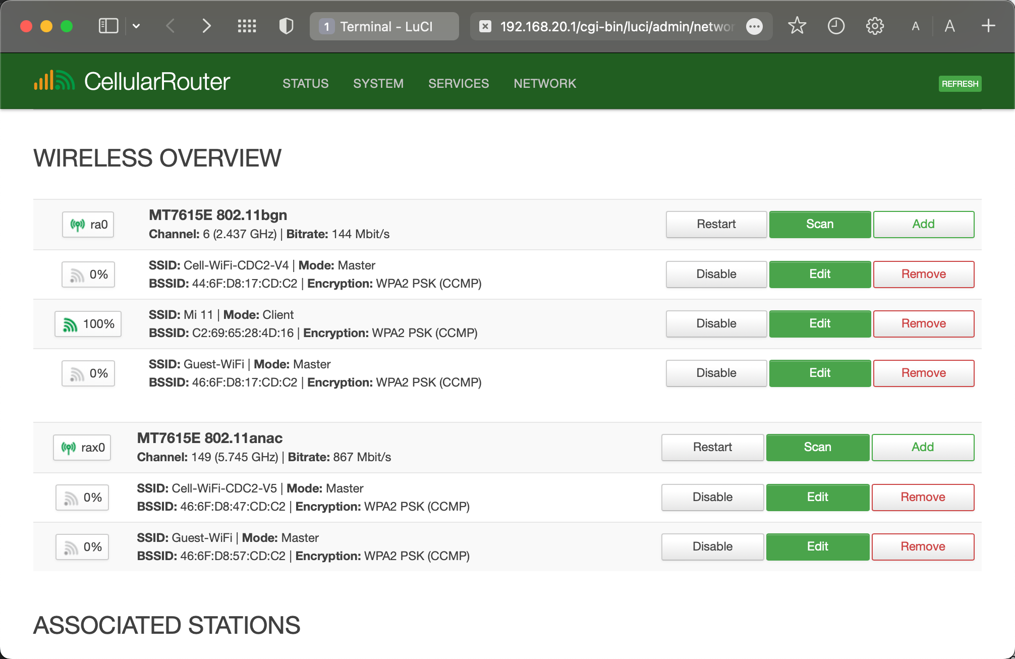
<div align="left"><figure><img src="/files/Eqe5vvcXz2ssbFizMmNl" alt="" width="375"><figcaption><p>Refresh the Wireless Overview Page</p></figcaption></figure></div>

Navigate to the wireless overview page within "Network > Wireless." Refresh the web page and patiently wait for a few seconds until you locate "Guest-WiFi" listed under both b/g/n and an/ac hotspots. Modify their ESSID hotspot names and encryption passwords according to your preferences.

***

## Manual Operation

### Create Interface

Establish a new interface for the Guest network by navigating to "Network > Interfaces" and selecting the "Add New Interface" option.

Specify a "Name for the new interface" using letters, numbers, or underscores.

Under the "Cover the following interface" section, scroll through the dropdown menu to "Custom Interface" and input "eth0.100"; subsequently, press Enter on the keyboard.

Complete the process by clicking the "Submit" button.

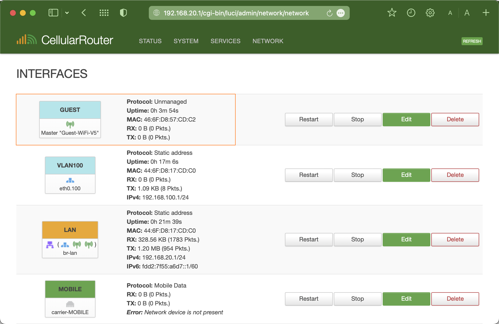
![](/files/2cxaOeRY0UstiEtx52AX)![](/files/KSXalXBTrACFjPbDE8Vv)

Then, it jumps to the new interface configuration page. Set the "IPV4 Address" to "192.168.100.1", and select "255.255.255.0" for the "IPV4 Netmask.

Click the "Firewall Settings" tab and choose "Guest" on the Firewall-zone option.

Then click the "Save & Apply" to perform the new interface settings.

### Switch VLAN

VLANs are frequently used to separate different network segments, and the router is equipped to support multiple VLANs, enabling direct communication between devices within each VLAN.

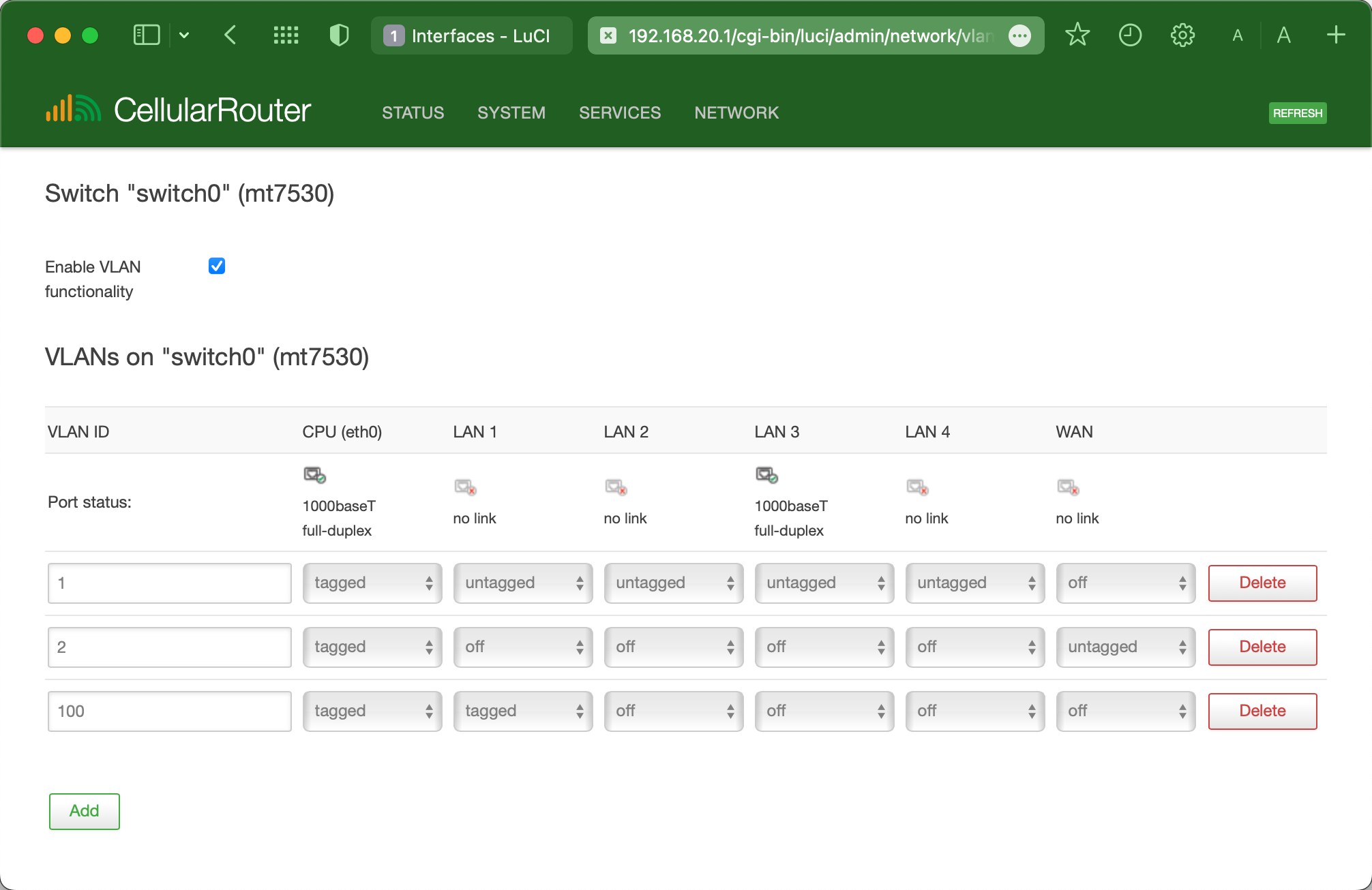
To configure VLAN for the Guest WiFi, navigate to "Network > Switch," and incorporate the previously established Guest interface "vlan100" by clicking the "Add" button.&#x20;

* Set the VLAN ID to 100, matching the previously configured interface.&#x20;
* For CPU (eth0) and LAN1, select "Tagged." Keep the remaining options set to "off."

Then click the "Save & Apply" button.

<div align="left"><figure><img src="/files/AENGireZehqjGPY0CVsk" alt="" width="375"><figcaption><p>Switch VLAN for Guest Interface</p></figcaption></figure></div>

### New Hotspot

Visit the wireless hotspot overview page on "Network > Wireless." On the right side of either the 2.4G (b/g/n) or 5.8G (an/ac) hotspots, click the "Add" button.

<div align="left"><figure><img src="/files/ZtVziSzknG72BNqH3zIb" alt="" width="375"><figcaption><p>Add New WiFi Hotspots</p></figcaption></figure></div>

#### General Setup

Maintain the "General Settings" without any alterations. These frequency modes, channels, bandwidth, and transmit power settings are linked to the primary WiFi hotspot.

#### Interface Configuration

Scroll down to the "Interface Configuration"

* **Mode:** Leave it unchanged. The Mode should be set to "Access Point".
* **ESSID:** Customize your Guest WiFi's hotspot name—e.g., Guest-WiFi-V5.
* **Password:** Navigate to the "Wireless Security" tab to choose the Encryption type and enter the WiFi password into the "Key" field.
* Click the "Save" button. Avoid clicking the "Save & Apply" button, as it will trigger a complete reboot of the WiFi function.

![](/files/AkG8V9dZic2pa9tqXS7c)![](/files/NAfZBPMk1qPVksIN9JjF)

After returning to the wireless overview page, select the "Edit" button adjacent to the recently added Guest-WiFi-V5. Within the "Network" category, generate a new network labeled "guest." Subsequently, press the "Save & Apply" button to initiate a WiFi function reboot.

<img src="/files/yz05nT6rpyQ8IA13x2wG" alt="" data-size="original"><img src="/files/iPSYSkVDX6psKzsFq8Bj" alt="" data-size="original"><img src="/files/YYZpD01SqJEYzATuRk0m" alt="" data-size="original">

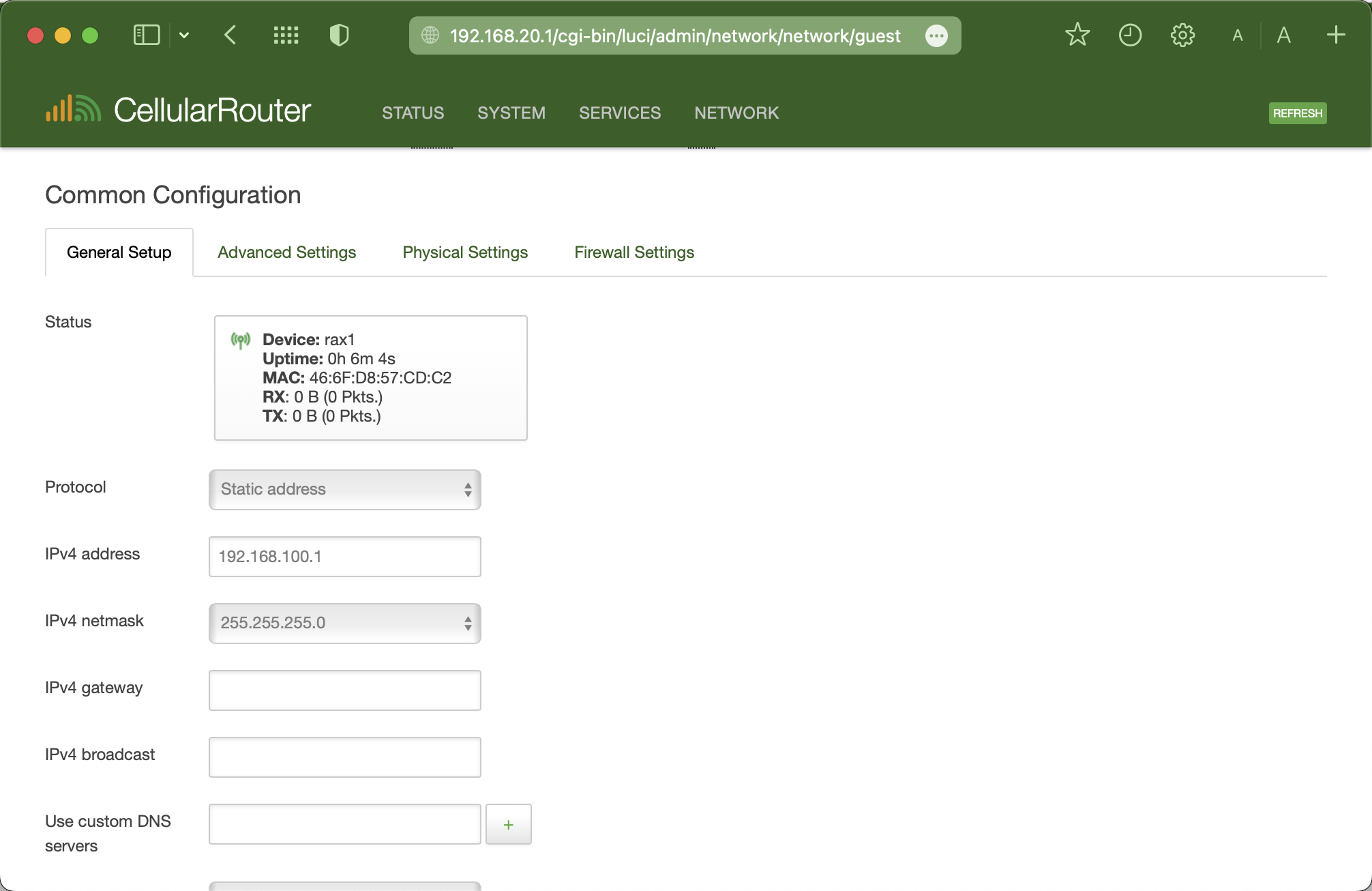
Go to the interface overview page under "Network > Interfaces" and click the "Edit" button on the "Guest" interface. Choose "Static Address" on the protocol, and click the "Switch Protocol" button.

Enter "192.168.100.1" as the IPv4 address and choose "255.255.255.0" for the IPv4 netmask. Save the settings by clicking "Save & Apply."

Note: Keep the DHCP Server section below enabled. Disabling the DHCP server will result in the Guest interface no longer assigning local IPs to guest devices.


# Parent Control

To prevent specific Mac addresses from accessing the WiFi hotspot in particular time periods, for example, blocking kids from playing phones, tablets, and computers when they should sleep.

It supports EZEN4X series routers, as shown below. This script does not support the EZEN3X routers. Please follow the below steps to install, configure, and activate the parent control function.

<table><thead><tr><th width="175">Firmware</th><th>SKU Models</th></tr></thead><tbody><tr><td>EV4xxx</td><td>EZR14(T), EZR24, EZR34(T)</td></tr></tbody></table>

{% hint style="info" %}
This is a temporary script-level solution. It is required to access SSH terminals, and no Web UI is available yet.
{% endhint %}

***

## Install Script

After [accessing the SSH terminal](/dev/ssh), run the installation command below.&#x20;

{% code title="EZEN4X Routers Only!" overflow="wrap" %}

```html
wget http://www.outdoorrouter.net:8080/Scripts/blacklist.sh -O /root/blacklist.sh; chmod 755 blacklist.sh
```

{% endcode %}

You will see confirmation output upon successful application loading as below.

If errors appear during the download and installation, please copy the returned information and forward it to our support team.

{% code title="Output Example" %}

```
Downloading 'xxx.sh'
Connecting to xxx
Writing to '/root/blacklist.sh'
Download completed
```

{% endcode %}

***

## Configure Script

We need to add specific Mac addresses to the blacklist.sh. You can find the Mac address of a terminal device in its WiFi (internet) status or settings. When the device is already connected to the router, you can check their Mac address on "Active DHCP leases" under "Network > DHCP and DNS."

After having the Mac addresses, go back to the SSH terminal and execute the below command to open the newly installed blacklist configuration file.

```
vi /root/blacklist.sh
```

Refer to the [VI Editor tutorial](/dev/ssh/vi) to edit the Mac addresses on line 4 and separate them with Space. Then, save settings and exit the VI editor.

{% code title="Default Values" lineNumbers="true" %}

```html
#!/bin/sh
. /lib/functions.sh

maclist="AA:BB:CC:DD:EE:FF 00:11:22:33:44:55 66:77:88:99:00:11"
ifnames="ra0 ra1 rax0 rax1"
```

{% endcode %}

***

## Scheduled Task

The final step is to set scheduled tasks to start and stop the above-configured blacklist.sh. Navigate to "System > Scheduled Tasks" to add cron jobs.

The below example is to start the task at 10:00 PM and end the task at 07:00 AM. Please refer to the [Crontab Syntax](/dev/ssh/cron) to customize the period.

{% code title="Bock WiFi 10pm to 7am" %}

```html
0 22 * * * sh /root/blacklist.sh start
0 7 * * * sh /root/blacklist.sh stop
```

{% endcode %}


# Traffic Control


# IP and DNS

## IP Address

An **IP (Internet Protocol) address** is a unique numerical label assigned to each device connected to a computer network that uses the Internet Protocol for communication. It serves as an identification and location system for devices on the internet or a local area network (LAN).

### Public IP

Public IP, also called External IP, is a unique numerical identifier used on the Internet provided by an Internet service provider (ISP).

A public IP address is unique and used to access the Internet. It is also used by other devices and websites to identify and communicate with devices connected to a local area network. A public IP address ensures that websites, email, and other online content reach you correctly, acting as a gateway to the Internet.

In general, additional security measures are required when using a public IP address to provide services over the Internet, such as using a firewall to close unused ports and protocols and using a DMZ network segment to separate public services from the LAN.

### Private IP

Private IP, also called Internal IP, does not travel on the Internet, never leaves the local network, and cannot be used to exchange traffic.

On the same local network, the private IP address must be unique. Users cannot access the Internet from a private IP address. Instead, they must connect to the Internet through NAT, which replaces the private IP address with a public IP address. Therefore, NAT hides private IP addresses and increases network security. The network and router assign a private IP address to the device. When receiving or sending data, the private IP address plays a role in the local network, while the public IP address is used to communicate over the Internet.

Standard private IP address formats include the following:&#x20;

* 10.0.0.0 to 10.255.255.255
* 172.16.0.0 to 172.31.255.255
* 192.168.0.0 to 192.168.255.255
* 100.64.0.0 to 100.127.255.255 (Carrier-Grade)

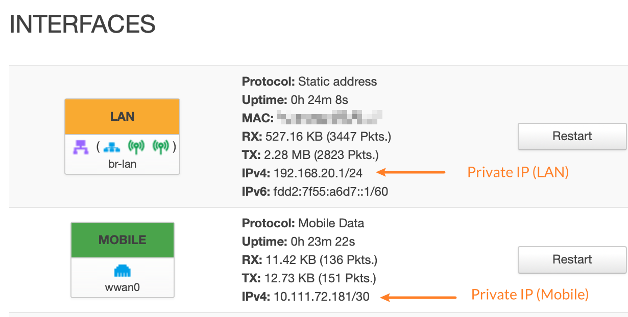
Below is an example of a 5G SIM card router. The router's LAN IP is 192.168.20.1, and the Mobile modem has obtained a private IP of 10.111.72.181 from the carrier. Both are private IP addresses.&#x20;

<figure><img src="/files/gO6xtvnAJuo3tbNDHLje" alt=""><figcaption><p>IP Address Example on 5G SIM Card Router</p></figcaption></figure>

&#x20;&#x20;

### Compare

These private IP addresses are used exclusively for internal network communication and are not routed over the public Internet. In contrast, public IP addresses are globally unique and are used for communication and identification over the Internet.

Specifically, public IP addresses are used to connect to the Internet, enabling devices to communicate with other global devices and access websites and online services. Private IP addresses are used to connect local devices, such as computers, mobile phones, and printers, for internal data exchange and communication.

Another important difference is that public IP addresses are globally unique; each device has a different public IP address on the Internet, while private IP addresses can be reused within the local network as long as they remain unique within the local network.

***

## DHCP

DHCP, short for Dynamic Host Configuration Protocol, is a network management protocol. Its primary function is to automatically assign IP addresses, subnet masks, default gateways, and other network configuration parameters to devices connected to the router's network.

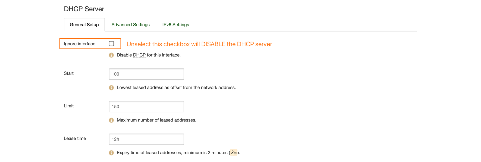
To custom or verify the DHCP settings on the OutdoorRouter, navigate to "Network > Interface > LAN: Edit," scroll down, and find the DHCP server section, as the image below shows.&#x20;

<figure><img src="/files/vxEzhvDzJdsZfT2RCOxo" alt=""><figcaption><p>LAN Interface DHCP Server Settings</p></figcaption></figure>

Explanation of DHCP Parameters

<table><thead><tr><th width="117">Field</th><th width="87">Default</th><th>Description</th></tr></thead><tbody><tr><td>Start</td><td>100</td><td><p>The start of the DHCP IP pool.</p><p>For example, if the router’s LAN IP is 192.168.20.1 and the netmask is 255.255.255.0, a valid IP address should be in the range of [192.168.20.100…192.168.20.249]</p><p>* <em>192.168.20.255 is a particular unavailable address.</em></p></td></tr><tr><td>Limit</td><td>150</td><td><p>Define the IP addresses the DHCP server can lease out.</p><p>Continuing from the above example, if the start address is 192.168.20.100 and the server can lease out 150, available addresses will be from 192.168.20.100 to 192.168.20.249.</p></td></tr><tr><td>Lease Time</td><td>12 hours</td><td><p>The duration of an IP lease. Leased-out addresses will expire after the specified period, and a new DHCP lease must be requested.</p><p>If the device stays connected, its lease will be renewed after half the specified time passes.</p><p>For example, if the lease time is 12 hours, then every 6 hours, the device will send a request to the DHCP server asking to renew its lease.</p><p>The lease time can be set in hours (h) or minutes (m). The minimum time that can be specified is 2min (2m).</p></td></tr></tbody></table>

### Static IP

A static IP address is a permanent, fixed Internet Protocol (IP) address assigned to a device on a network. Unlike dynamic IP addresses, which are temporarily assigned and can change over time, static IP addresses remain constant and do not change unless they are manually reconfigured.

Both the above-mentioned public IP and private IP can be static IP types. We usually set private static IPs in our local network to simplify network management.&#x20;

We can force the router to always release the same static IP to specific devices. To customize the static release on the router, please follow the steps below.

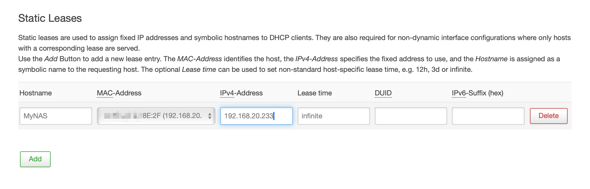
1. Go to "Network > DHCP & DNS" and scroll down to the "Static Leases" section.
2. Click the "Add" button to input a new static IP rule.
3. Hostname: Input name of the device\
   MAC-Address: Choose from the dropdown list or input after choosing "--custom--"\
   IPv4-Address: Choose from the list or input a new IP after choosing "--custom--"\
   Lease time: Use "12h" or "48h" for lease 12 hours or 48 hours.\
   We can also use "**infinite**" to release the static IP forever.
4. Click "Add" if need to set more static lease rules.
5. Click the "Save & Apply" button to take effect.

<figure><img src="/files/d3V0REs7f9hXHBzEFRVp" alt=""><figcaption><p>DHCP Static Leases Rules</p></figcaption></figure>

**How to configure static IP on terminals?**

Ensure the gateway IP address and subnet mask address match the router's IP pool. Below is an example of an indoor SIM card router.

Computer IP: 192.168.20.100 (Inside the default DHCP range of 100\~249)\
Subnet Mask: 255.255.255.0 (also called 24 on Windows)\
Gateway (Router IP): 192.168.20.1

**On iPhone** -- Go to "Settings > Wi-Fi > Advanced." \
**On Android** -- Go to "Settings > WLAN > Advanced." \
**On Mac** -- Go to "System Preferences > Network > Wi-Fi > Advanced > TCP/IP."

**On Windows PC** -- Go to "Start > Control Panel > Network & Internet > Change Adapter Settings. Change the "Local Area Connection > Properties (on the right click) > TCP/IPv4 > Properties > General". Enter the above static IP address, subnet mask, and gateway. Click "OK" to exit settings.

***

## DNS

DNS, short for Domain Name System, is used to name machines on the Internet. Just like visiting friends to say goodbye to how others go, when a host wants to visit another host on the Internet, it must first know its address, and the IP address in TCP/IP is composed of four paragraphs. Separate number composition (IPv4 address as an example, IPv6 address), remember, is not always as convenient as the name, so the domain name system is used to manage the corresponding relationship between name and IP.

Although all nodes on the Internet can be identified by and accessed through IP addresses, even a 32-bit binary IP address written as four ten digits of 0 to 255 is still too long and difficult to remember. Therefore, Domain names were invented to associate an IP address with a set of meaningful characters. When users visit a website, they can enter the website's IP address or domain name, which is equivalent to access.

### Custom DNS

If you are on the same network, you may encounter that all other devices can access the Web page, but one computer or mobile phone can not. In this case, you can check whether the mobile phone or computer's DNS configuration is correct or manually add the DNS server address.&#x20;

For example, we can use Google public DNS of 8.8.8.8 and 8.8.4.4 to avoid DNS resolving problems. Some websites or applications require specific DNS resolution. You can consult your ISP or mobile carrier for details.

We can either set custom DNS servers on the phones and computers or set custom DNS on the router. Then, we will use the DNS resolving services from the custom DNS server instead of the ISP or carrier's DNS service.&#x20;

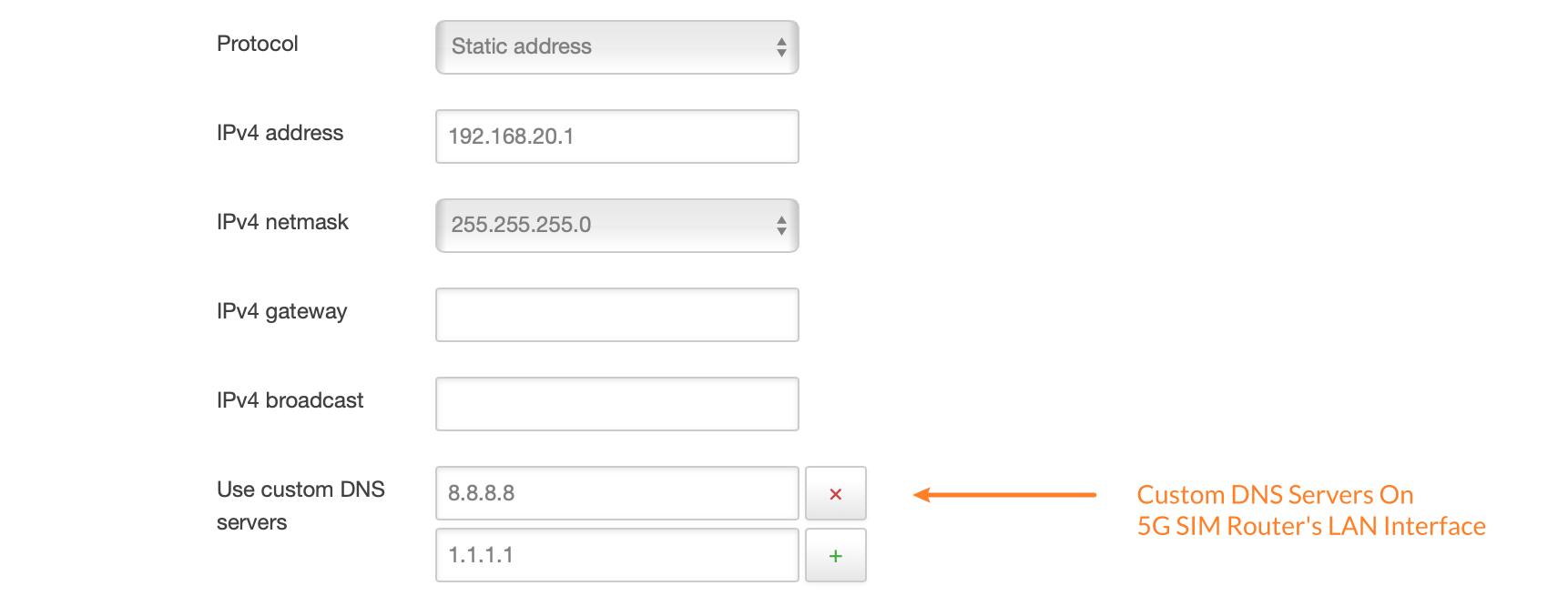
To custom the router's DNS settings, log into the router and follow the below steps:

1. Navigate to "Network > Interfaces > LAN: Edit"
2. Input the DNS on the field "Use custom DNS servers."
3. Click the "+" button to add more.
4. Click the "Save & Apply" button on the bottom right corner to take effect.

<figure><img src="/files/qlRSHhfPWj0MTw3FB1zw" alt=""><figcaption><p>Add Custom DNS Servers On SIM Router's LAN Interface</p></figcaption></figure>


# SQM QoS

With SQM traffic control, you can enable traffic shaping, better mixing (Fair Queueing), active queue length management (AQM), and prioritization on one network interface.

**SQM** - Smart Queue Management\
**QoS** - Quality of Service

## Introduction

The OutdoorRouter SQM QoS is an advanced Quality of Service that provides better internet traffic shaping and bandwidth management. Here are the key features of it.

The SQM function intelligently manages buffer bloat on the router network. Bufferbloat is the excessive buffering of packets that can cause network congestion and high latency. SQM dynamically adjusts buffers to optimize performance.

When enabled, the router prioritizes latency-sensitive traffic, such as gaming, voice calls, video chatting, etc, which need low network latency. SQM can detect this traffic and prioritize it over bulk transfers and downloads to ensure a better experience.

It also minimizes the impact of bandwidth-intensive transfers. For example, large downloads and transfers can congest a network. SQM makes sure they don't choke out low-volume interactive traffic.

## Bandwidth Limit

The SQM QoS functionality on OutdoorRouter allows setting customized bandwidth limits for specific network interfaces.&#x20;

For example, throttling speeds on the Guest WiFi interface can ensure guest devices do not consume excessive bandwidth. To set bandwidth limits for the Guest WiFi network:

1. Go to "**Network > SQM QoS**" in the router admin panel after logging in.
2. Under the "**Basic Settings**" tab, select the "**wlan0-1 (Guest)**" interface. This corresponds to the Guest WiFi network.
3. Enter the maximum download and upload internet speeds you want to allow for Guest WiFi clients. Set these limit values individually in *Kbits/sec*.\
   For example, you can set the Download Speed to "2048" and the Upload Speed to "1024". This will throttle Guest WiFi speeds down to 2Mbps down and 1Mbps up.
4. Click "Save & Apply" at the bottom once the speed limit values are entered in Kbits/sec for download and upload.

<div align="left"><figure><img src="/files/5Q21rqneDuovV20qjgr3" alt="" width="375"><figcaption><p>Network > SQM QoS > Throttle Guest Interface</p></figcaption></figure></div>

By applying throttling, guest devices will be restricted to the defined maximum internet speeds. This prevents them from taking up significant bandwidth that may slow down internet performance for primary devices and networks connected to the router. It is an effective way to optimize internet traffic flows across different user groups.

<div align="left"><figure><img src="/files/HOdXXCXjDWrWROisvtwH" alt="" width="375"><figcaption><p>Network > Wireless > Guest WiFi Device Speed Rates</p></figcaption></figure></div>


# Load Balancing

A dynamic and flexible mechanism to distribute network traffic across multiple internet connections.

## Multiple WAN

The load balancing feature manages multiple Internet connections, encompassing various sources such as wired landline connections through the **WAN** port, **mobile** modems, and wireless **WiFi relays**.

*Note: You can skip this section if your router has a single Internet connection.*\
*Incorrectly configured settings may lead to issues, particularly when non-functional Internet links are falsely enabled, potentially disrupting the router's Internet connectivity.*

When the router has multiple internet connections and load balancing is disabled, the router will use all the enabled Internet links and allocate network traffic based on their respective interface metrics.&#x20;

For instance, if the WAN metric is set to 1 and the mobile metric is set to 3 on default settings. The lower number takes precedence, indicating higher priority for that connection in traffic distribution.&#x20;

In such cases, activating the load balancing function allows for the distribution of network traffic according to predefined policies and the current state of each connection. This enables the optimization of bandwidth utilization and improvement of network performance.

***

## Basic Introduction

Go to "Network > Load Balancing" after logging into the router to enable and configure the load balance function. Below is a fundamental overview of key components within the load balancing system.

### **Interfaces Overview**

Navigate to the "Interfaces" default tab and review the "MWAN - Interfaces" overview page to identify the supported internet sources on the router.

* WAN - A wired connection linked to the WAN port from a landline modem or another internet router.
* MOBILE - Mobile internet accessed through the mobile modem of OutdoorRouter.
* WWAN - Wireless WiFi relay (repeater) connected to another router's WiFi hotspot.

#### Enable Internet Interface

The "Enabled" header in the "MWAN - Interfaces" chart signifies the status of the internet source managed by the load balancing feature. All the interfaces are disabled on default settings.&#x20;

When you have more than one relative internet connection activated, click the "Edit" button of the interface. Choose "Yes" on the Enabled option. Then click the "Save & Apply" button to enable the internet interface.

<div align="left"><figure><img src="/files/O1Nm6mwFbTCLnDddA6qB" alt="" width="375"><figcaption><p>Load Balancing - Mwan Interfaces Overview</p></figcaption></figure></div>

### Metric & Weight

Navigate to the "Members" tab to review each interface's network metrics and traffic weight within the load balancing system. The chart below displays the default values, where the lower number holds priority.

Suggest to retain the default metric and weight settings. In the subsequent "Policies" settings step, you can establish the order for traffic connections.&#x20;

To utilize all traffic sources concurrently, set the members with identical metrics.

| Member Name | Interface | Metric | Weight |
| ----------- | --------- | ------ | ------ |
| wan\_m      | wan       | 1      | 1      |
| MOBILE\_m   | MOBILE    | 3      | 3      |
| wwan\_m     | wwan      | 2      | 2      |

### Policies

Access the "Policies" tab to examine the pre-configured policies and profiles.&#x20;

Policies serve as profiles that group one or more members, dictating how the load-balancing function allocates network traffic. The prioritization is based on lower metric values assigned to member interfaces.

You can create a new policy or modify an existing profile to specify the internet sources you wish to utilize. In the subsequent "Rules" step, the default configuration is set to employ the "ALL" policy, directing traffic through "WAN > Mobile > WWAN (WiFi Relay)".

### Rules

Click the "Rules" tab to check the load balancing rules.

The load balancing rules delineate the traffic designated for a specific policy and are determined by factors such as IP address, port, or protocol. These rules are sequentially matched from top to bottom, with any rules beneath a matching one being disregarded. Traffic that doesn't correspond to any rule follows the routing path outlined in the main routing table.

You can either establish a new rule or modify the "default\_rule." Select the policy you defined in the preceding step from the "Policy Assigned" dropdown.

<br>

### Global Settings

You can disregard the "Global" setting tab in the latest firmware version. Click the "Enable" checkbox for older firmware versions to activate the load balancing function. There is no requirement to reboot the router for the load balancing to take full effect.

***

## Status & Debugging

Navigate to "Status > Load Balancing > Tab: Interface" to assess the operational status of each internet source.&#x20;

* The "Status" indicator reveals whether the interface is active.&#x20;
* A green background signifies that the internet ping tests have been successful, confirming a functional internet connection.

Click the "Detail" tab to check the interface status and assigned policies.


# Intranet Routes

Manually configured routing entries in the router's routing table to define where to forward network packets destined for specific IP address ranges or networks.

The "Static Routes" allows access to specific devices across different routers. For example, if device A connects to the outdoor router, as the image below shows, and requires access to device B, which is linked to another indoor router, we need to set static IP and static routes, as the below step shows.

<figure><img src="/files/Gh3nzFs6AM94QL9A5Wd2" alt="" width="375"><figcaption></figcaption></figure>

## Static IP

Go to the OutdoorRouter and set a static IP for the IndoorRouter.&#x20;

Log into the OutdoorRouter and navigate to "Network > DHCP AND DNS." Then, scroll down to "Static Leases" and click the "Add" button.

1. Hostname - Name to indicate the indoor router.
2. MAC Address - Choose the correct address of the indoor router.
3. IPv4 Address - The static IP address assigned to the indoor router.
4. Lease Time - Use "infinite" to permanently release the static IP to the indoor router.&#x20;
5. Click the "Save & Apply" button on the bottom right corner to finish the static IP settings.

<figure><img src="/files/4IqE9J7CDHuOsuqnAyGW" alt=""><figcaption></figcaption></figure>

## Static IPv4 Routes

Navigate to "Network > Static Routes" to customize the routing to the IndoorRouter.

1. Interface - use LAN
2. Host-IP - The indoor router's IP address. For example, 192.168.1.1.
3. IPv4 Netmask - The indoor router's subnet mask. Suggest using the same subnet on the indoor router, which is 255.255.255.0.
4. IPv4 Gateway - The WAN IP address previously set in the step of Static IP.
5. Click the "Save & Apply" button.

<figure><img src="/files/fXgVA2piZyOlNzJhNecu" alt=""><figcaption></figcaption></figure>

## Turn Off WAN NAT

To successfully route from upstream OutdoorRouter, we need to turn off the NAT on the WAN interface of the IndoorRouter. This setting usually appears under the WAN interface or firewall settings. Locate the "NAT" or "Masquerade" switch and turn it off.

If unable to find the NAT switch, contact the seller of the IndoorRouter for technical assistance.


# Traversal Cloud

Traversal Cloud is a secure NAT tunnel tool to provide remote control function on the outdoor router.

The **Traversal Cloud** provides secure remote access to Outdoor Routers over the internet without needing public IP. This cloud-based service creates an encrypted tunnel from the router to the Traversal Cloud servers.

After enabling Traversal Cloud in the router web admin at "Services > Traversal Cloud", you can access and manage the router securely from anywhere by visiting its unique cloud address on a web browser. It offers the easiest way to look over your networks. No public IP address and DDNS configuration are required.

<figure><img src="https://www.outdoorrouter.com/wp-content/uploads/Traversal-Cloud_NAT-Tunnel-Tool_Outdoor.jpg" alt=""><figcaption><p>How Traversal Cloud Works?</p></figcaption></figure>

## Enable

The traversal cloud is turned off by default. Before allowing remote access, be sure to configure the router with a strong router password. You can follow the below steps to enable it.

1. Log in to the router admin and go to "Services > Traversal Cloud."
2. Click the " Enable " checkbox and "Save & Apply" to activate the Traversal Cloud.
3. Reboot the router if it was previously disabled to refresh the tunnel.
4. Visit the router's displayed cloud browser address or enter its unique URL from any internet-connected computer to access the web admin remotely.

Note: Cellular carriers may occasionally block the standard Traversal Cloud ports, disabling connectivity.

<div align="left"><figure><img src="/files/bao5zVe2BPYcB99UgdMO" alt="" width="375"><figcaption></figcaption></figure></div>

## Debug

If unable to connect through the cloud tunnel, please check the below factors:

* Confirm the Traversal Cloud feature is enabled in the router admin and that the router has a working internet connection.
* Reboot the router if previously disabled.
* Copy and send the router's system log to us for technical assistance if it is still non-functional.


# Ezen Cloud

One Platform to Manage All Your Routers and Linked Devices - With one cloud dashboard reaching your whole routing infrastructure.

## Introduction

EzenCloud is a centralized cloud platform enabling you to administer all your 4G, 5G, WiFi routers, and range extenders from a unified interface. EzenCloud provides remote access for convenient web-based management no matter where devices are physically deployed.&#x20;

* Connect remotely to the web interface without public IP addressing or port forwarding.&#x20;
* It also enables remote command line SSH sessions to routers for debug-level controls.&#x20;
* Furthermore, it allows remote access to LAN devices connected to the router.

## Beta and Demo

The EzenCloud management platform is currently in beta testing, and we're inviting customers to evaluate it firsthand with free demo accounts.

Please [contact us](https://www.outdoorrouter.com/contacts/) to sign up for the program and receive a token for a demo account. We will set up a trial account tied to your hardware MAC address. It supports all of our routers, as shown below, that are currently in production.

<table><thead><tr><th width="140">Firmware</th><th>SKU Models</th></tr></thead><tbody><tr><td>EV3xxx</td><td>EZR13(T), EZR23(T), EZR30, EZR33(L/T)</td></tr><tr><td>EV4xxx</td><td>EZR14(T), EZR24, EZR34(T)</td></tr></tbody></table>

Retrieving the LAN MAC address of your router is simple. Head to the "Network > Interfaces" page on your admin console and note down the string of numbers and letters listed for the "LAN" interface. Supply that to our staff upon requesting demo registration.

Within 24 hours, we will enable a hosted EzenCloud sandbox pre-linked to your provided MAC Address. You can then explore the platform's capabilities on your gear.

<div align="left"><figure><img src="/files/1CJOUGq50qI2hHjv0eTk" alt="" width="375"><figcaption><p>Obtain LAN Interface MAC Address</p></figcaption></figure></div>

## Install Plugin

Connecting your router to the EzenCloud platform requires installing a specialized plugin to enable communication. Use the [SSH terminal](/dev/ssh) to access your router's command line and run the appropriate installation command below based on your model series. This will safely download the plugin and integrate it with the system.

{% code title="EV3xxx Routers" %}

```html
opkg --force-overwrite install http://www.outdoorrouter.net:8080/EzenCloud/ezencloud_3x_v2.0.ipk
```

{% endcode %}

{% code title="EV4xxx Routers" %}

```html
opkg --force-overwrite install http://www.outdoorrouter.net:8080/EzenCloud/ezencloud_4x_v1.0.ipk
```

{% endcode %}

You will see confirmation output upon successful application loading as below.

If errors appear during the automated process, please copy the returned information and forward it to our support team.

{% code title="Output Format Example" %}

```html
Downloading xxxx.ipk
Installing ezencloud (x.x) to root...
Configuring ezencloud.
```

{% endcode %}

## Link to EzenCloud

After installing the EzenCloud plugin, refresh the router web page and go to "Services > Ezen Cloud" to connect with the platform. Ensure internet connectivity via wired WAN, mobile modem, or WiFi relay connections.

<div align="left"><figure><img src="/files/CUO63a9gi8ec7CLoNrn7" alt="" width="375"><figcaption><p>EzenCloud - Obtain Token Code</p></figcaption></figure></div>

### Obtain Token

Navigate to the Cloud Users section and click the "**Obtain Tokenstr**" button. The token is bound to your router hardware MAC address.&#x20;

* If it can not obtain a token code, check your internet connection, refresh the web page, and try again.
* If you got an error of "*Error: HaveNoTokenstr*," it means this router is not registered. Please verify the MAC address of the LAN interface and ensure the MAC address is the same as you submitted for the demo test.

### Register Account

If you have not signed up for an EzenCloud account, click the "**Register Account**" button. You will be redirected to create your user profile with a custom username and password.

<div align="left"><figure><img src="/files/6lEi1fMWU3mbBrgGHSye" alt="" width="375"><figcaption><p>Register An Account on EzenCloud Platform</p></figcaption></figure></div>

### Cloud Service

To enable communications with the EzenCloud platform, navigate to the "Ezen Cloud > Cloud Service" section in your router's web interface. &#x20;

**Enable / Disable** - You can manually toggle the service On or Off using the "Enable" checkbox. Click the "Save" button after changing the status to apply settings.

**Cloud Service Status** - Monitor the "Cloud Service Status" to validate the connectivity. The chart below explains different statuses for easy debugging. It should show "Bound" before remote access becomes available in your EzenCloud dashboard.

<table><thead><tr><th width="169">Status</th><th>Explain</th></tr></thead><tbody><tr><td>Off</td><td>EzenCloud plugin is turned off on the router.</td></tr><tr><td>Requesting</td><td>Checking the EzenCloud status.</td></tr><tr><td>Idle</td><td>The EzenCloud plugin is turned on but not bound to any EzenCloud account.</td></tr><tr><td><strong>Bound</strong></td><td>Displays a successful connection handshake with the EzenCloud server.</td></tr><tr><td>Inactive</td><td>The EzenCloud plugin is turned on and bound to an account, but there is no internet connection to communicate with the EzenCloud platform.</td></tr></tbody></table>

***

## EzenCloud Platform

You can now log in to **im.ezencloud.com** using your newly registered account and instantly access your router through the cloud. Manage, monitor, and update your device remotely from there!

<div align="left"><figure><img src="/files/PE8k5Wt5GWCsZxW3RAQQ" alt="" width="375"><figcaption><p>Log Into the EzenCloud Platform</p></figcaption></figure></div>

### User Account

EzenCloud allows you to customize your account credentials.&#x20;

**Edit Credentials** - Click "User List" in the left panel to access user management settings. Click the "Edit" button for the listed account name. You can modify the username or password associated with your EzenCloud user profile. The updated credentials will sync instantly with your EzenCloud account online.

**Subscription** - The default subscription provides the Participant role, which enables managing a single user account tied to your router. If your organization requires administering multiple user profiles across devices, contact our sales team to discuss upgrading your group permissions.

<div align="left"><figure><img src="/files/PkjrEkOucIkuAJUT6L0b" alt="" width="375"><figcaption><p>EzenCloud User Management Panel</p></figcaption></figure></div>

### Device Management

#### Device List

EzenCloud consolidates vital status visibility across all your connected routers in one dashboard. Click "Device List" " in the left menu to centrally track hardware units and connectivity.

The overview displays every router by its unique MAC address along with real-time parameters:

* **Status** - Green signifies an active tunnel to the router. Red means connection lost; verify the router's internet connection and enable the EzenCloud plugin.
* **Traffic** - Monitor monthly and daily data usage per device.
* **Runtime** - Check how long each router has maintained its "Latest Contact" time.

<div align="left"><figure><img src="/files/lJtcNO55UepebTh5luYu" alt="" width="375"><figcaption><p>EzenCloud Device List Overview Page</p></figcaption></figure></div>

#### Add Device

EzenCloud allows you to easily add additional routers to be managed collectively under your account.

Navigate to "Add Device" in the left panel and input the "TokenCode" from the router's onboard EzenCloud plugin interface.

The router is seamlessly linked to your existing account after entering the unique authentication string and clicking the "Save" button.

![](/files/wzNLsRz2tCzmqfROsToP)![](/files/igZFwppi9u315yW8ZFrD)

### Remote Access

The EzenCloud platform enables simple, secure remote access to all your routers with a few clicks. An authenticated connection will open directly into that unit's admin console, presenting full controls as if locally connected.&#x20;

1. Navigate to "Device List" and check the routers in a green status with an active cloud tunnel.
2. Click the "Access" button for a specific online router to the remote access panel.

<figure><img src="/files/VyEmwhazKrQJ1nRNZink" alt=""><figcaption><p>Remote Access Router's Web Interface &#x26; SSH Terminal</p></figcaption></figure>

#### Web Access

Click "Start Web Access" to remotely log in to the router's web admin console.

EzenCloud assigns a temporary port to tunnel traffic securely through the cloud. Use your router's normal admin password to log into the router remotely.

#### SSH Terminal

To access the router's SSH terminal, go to the "Terminal Access" section:

* Choose "Router Public IP" and input "localhost";
* Terminal Port - Input the router's SSH port number. The default port is 22.
* Click the "Create Terminal Link" button to generate a temporary port number.

Then, you can access the router's SSH terminal with the information below.

> *Host: im.ezencloud.com*\
> *Port: 36179 (example - depends on the actual port number it generated)*

#### Local LAN Access

To access the LAN devices connected to the router, you can use its MAC address or local IP assigned by the router.

* Choose "Router Public IP" and input the local IP address\
  Or choose "Router MAC Address" and input the MAC address, excluding colon, of the LAN device
* Input the LAN device's exposed Port number into the "Terminal Port."

To remotely access web, SSH, and LAN devices, ensure the router is in the "Online" status. If an "Offline" error occurs, please check the internet connection status on the router.

Don't hesitate to [contact us](https://how.router.works/remote/www.outdoorrouter.com/contacts) with inquiries while using the EzenCloud plugin and platform. We appreciate any feedback you may have after testing the platform.


# VPN Tunnel


# ZeroTier

ZeroTier is a software-defined networking (SDN) solution that creates secure virtual networks using encrypted P2P tunnels, without requiring public IP addresses.

By joining a ZeroTier network, your router acts as a traffic gateway, enabling remote LAN access or interconnecting subnets across physical locations.

## Example of Setting ZeroTier

Navigate to the router menu: SYSTEM > Terminal. Enter the username root and log in with the password you set.

### 1. Zerotier Management

Visit [www.zerotier.com](https://www.zerotier.com) and log in.&#x20;

You will notice that networks are already configured by default. Select one of these or create your network, then save the Network ID.

&#x20;![](/files/Rk6BhGxvoRbgt9ZcenLX)

### 2. Install ZeroTier

All commands are executed in the SYSTEM >Terminal section of the router menu.

```
opkg update
opkg install zerotier
```

### 3. Enable the ZeroTier

Since ZeroTier is disabled by default, we need to activate the ZeroTier service.

```
uci set zerotier.sample_config.enabled='1'
uci commit zerotier
/etc/init.d/zerotier restart
```

### 4. Join Network

zerotier-cli join \<Network ID>&#x20;

Here, we use the network with the ID 35c192ce9b1ff07f in step 1 as an example.

```
zerotier-cli join 35c192ce9b1ff07f
```

{% code title="Response" %}

```markup
200 join OK
```

{% endcode %}

### 5. Authorize Device

Click on the networks we have selected. You can view the member information in Members. Select the member and click the Authorize button to authorize the device.

<figure><img src="/files/ce21b4HFltZMFo0zqDvx" alt=""><figcaption></figcaption></figure>

Once authorized, we can connect with each other via the Managed IPs assigned by Zerotier.

We can customize IP addresses or specific policies through ZeroTier's management platform. Click Settings to manage Managed IPs, and click Flow Rules to view related policy information.

<figure><img src="/files/OsGz99EfC80FBzcYp8Sl" alt=""><figcaption></figcaption></figure>

To delete a member from the network, click the Edit button for that member, select the Delete Member option, and then click the Delete Member button.

<figure><img src="/files/ZMfdMmJR0pz1nCBcvft2" alt=""><figcaption></figcaption></figure>


# Tailscale

Tailscale is a VPN solution that provides seamless connectivity between devices across different networks without the need for public IP addresses or complicated firewall rules.

By joining a Tailscale network, your router can function as a subnet router, enabling remote access to local resources or securely connecting multiple subnets.

## Example of Setting Tailscale

Navigate to the router menu: SYSTEM > Terminal. Enter the username root and log in with the password you set.

### 1. Install Tailscale

All commands are executed in the SYSTEM >Terminal section of the router menu.

```
opkg update
opkg install tailscale
```

### 2. Enable the ZeroTier

Enable and start the Tailscale service.

```
/etc/init.d/tailscale enable
/etc/init.d/tailscale start
```

### 3. **Authenticate and Join Network**

Use this command to authenticate your device:

```
tailscale up
```

This command will generate a URL. Open the URL in your browser and log in with your Tailscale account to authorize the device.

<figure><img src="/files/DKsal3vizuZxJj9ndNhd" alt=""><figcaption></figcaption></figure>

### 4. **Configure as Subnet Router (Optional)**

If you need to expose the local subnet through Tailscale, use:

```
tailscale up --advertise-routers=192.168.30.0/24 --accept-dns=false
```

Replace `192.168.30.0/24` with your local subnet.

Prevent Tailscale's DNS Settings from disrupting your local network.

### 5. Enable Subnet Routes in Admin Console

* Visit the [Tailscale Admin Console](https://login.tailscale.com/admin).
* Go to **Machines**, locate your router device, and turn on the **Subnet routes** option.

<div align="left"><figure><img src="/files/RV2fubr4BJE5xD85u0Dt" alt=""><figcaption></figcaption></figure></div>

<div align="left"><figure><img src="/files/Bhny50rY0kQNT0axLhMM" alt="" width="305"><figcaption></figcaption></figure></div>

After completing the above settings, we can connect the remote device to the router and to the devices connected to it.


# Wireguard

WireGuard is a modern, high-performance VPN protocol that establishes secure point-to-point connections using advanced cryptography.

By setting up WireGuard tunnels, devices can securely communicate over the Internet or private networks, enabling remote access, site-to-site VPNs, and encrypted networking across distributed environments.

## Example of setting up Wireguard

{% hint style="info" %}
Please note that the example uses a router as the server, and the server must have a public IP address.
{% endhint %}

### 1. Generate the private key and public key

#### 1.1 Server Settings

Navigate to the router menu: SYSTEM > Terminal, enter the username: root, and log in with your set password.

```
wg genkey | tee privatekey | wg pubkey > publickey
cat privatekey
cat publickey
```

<figure><img src="/files/PnY6ypL2YdnPy4bY81NC" alt=""><figcaption></figcaption></figure>

Using the command above, you can generate and view the router's private and public keys, then save their information in a notepad.

#### 1.2 Client Settings

Here, WireGuard for macOS is used for demonstration.

Open WireGuard, click the + sign in the lower left corner, select Add Empty Tunnel, and the public and private keys for macOS WireGuard will be automatically generated, as shown in the following figure.

{% hint style="info" %}
If two routers are to establish WireGuard communication, the server settings above need to be repeated to generate the public and private keys using the command line.
{% endhint %}

<figure><img src="/files/gYB9WFpnDuNEZRXMtuGE" alt=""><figcaption></figcaption></figure>

### 2. Add the WireGuard interface

Navigate to the router menu bar NETWORK > Interface, click the Add new interface button at the lower left corner, enter a custom interface name such as wg0, select the WireGuard protocol, and click the Save & Apply buttons. Then it will automatically jump to the configuration page of the wg0 interface.

### 3. Set up the Wireguard interface

#### 3.1 General Setup

Private key: Paste the private key generated in Step 1\
Listening port: Use custom high-bit ports (such as 51820), avoiding common ports.\
IP address: Configure a dedicated VPN network segment (such as 10.0.0.1/24), ensuring it does not conflict with the existing local network.

<figure><img src="/files/ZOsjkiWkQ1nBpyBpc5jf" alt=""><figcaption></figcaption></figure>

#### 3.2 Peers Setup

Public Key: Client's public key (not the server's public key)

Allowed IPs: The IP address assigned to the client (such as 10.0.0.12/32)

Route Allowed IPs: This needs to be checked; otherwise, the client won’t be able to access the subnet

Endpoint Host: Fill in during client setup. This section can be left blank

Endpoint Port: Fill in during client setup. This section can be left blank

Persistent Keep Alive: Fill in 25 (Maintain connection in NAT environment)

{% hint style="info" %}
Note: You need to repeat this step for each new client added.
{% endhint %}

<figure><img src="/files/rkDGmdfJBZ9QMNnOs8nj" alt=""><figcaption></figcaption></figure>

### 4. Firewall Settings

#### 4.1 Open a listening port

Navigate to the menu bar NETWORK > Firewall, scroll to the bottom of the page, click the Add button below Zones, and then you will be redirected to the Zones Settings page.

Name: wgzone

Input: accept

Output: accept

Forward: accept

Masquerading: checked

MSS clamping:  checked

Covered networks: wg0 (the WireGuard interface created in Step 3)

Allow forward to destination zones: lan

Allow forward from source zones: lan

Finally, click Save & Apply.

<figure><img src="/files/b20asHcLFRVV66c1X5L6" alt=""><figcaption></figcaption></figure>

#### 4.2 Traffic Rules

In the menu bar NETWORK > Firewall, click the tab labeled Traffic Rules, scroll to the bottom of the page, enter the policy name and protocol under Open ports on router, and then click the Add button. It will automatically navigate to the policy Settings page.

<figure><img src="/files/FHjWNEuqYCt8sIp3BeGN" alt=""><figcaption></figcaption></figure>

Name: Allow-WireGuard

Protocol: UDP

Destination port: 51820

Just keep the other Settings as default. Click "Save & Apply" to save the Settings.

<figure><img src="/files/M5rnSZe4WOlD0BPbYnPY" alt=""><figcaption></figcaption></figure>

#### 4.3 Custom Rules

Set up NAT forwarding for bypass routing scenarios.

Click "Custom Rules" on the tab bar.

```
iptables -t nat -A POSTROUTING -s 10.0.0.0/24 -o br-lan -j MASQUERADE
```

After entering the command, click "Restart Firewall".

{% hint style="info" %}
10.0.0.0 is a VPN network segment.
{% endhint %}

<figure><img src="/files/5KbcPzhO0HbtY0xzOusN" alt=""><figcaption></figcaption></figure>

### 5. Client settings

Here, we use WireGuard on macOS as an example.

#### 5.1 Add Tunnel

Open WireGuard and add an Empty Tunnel, consistent with step 1.2 above.

<figure><img src="/files/kJUX59MswrHVUOs99423" alt=""><figcaption></figcaption></figure>

#### 5.2 Tunnel Settings

PrivateKey = QCqtyyhGWfci4xxxxxx(automatic generation)

Address: The IP address of the client is consistent with the Allowed IPs in step 3.2 above

DNS: The server-side LAN port IP address

PublicKey: Step 1.1 Public key information generated by the server

AllowedIPs: The IP network segment of the VPN channel and the network segment that communicates with the LAN port of the router

Endpoint: The server's public IP address or domain name, along with port 51820

PersistentKeepalive: Maintain connection in a NAT environment

As shown in the figure, collect the public key information generated by the server and complete the client settings.

<figure><img src="/files/LgZRinoWv9d0ccX2qHS2" alt=""><figcaption></figcaption></figure>

### 6. Verify wireguard

We can verify the connection status by pinging the server or client's Tunnel IP to confirm if the tunnel has been successfully established. Typically, after the settings are configured correctly, the Tx/Rx data will be visible on the WireGuard interface, as shown in the figure.

<figure><img src="/files/V1jJYabO5QQF2LXVBqbV" alt=""><figcaption></figcaption></figure>

<figure><img src="/files/YHXoLHUJeO46n1xBzBhs" alt=""><figcaption></figcaption></figure>


# Openvpn

OpenVPN  uses SSL/TLS to establish secure, encrypted tunnels. It supports both site-to-site and remote access setups, offering strong security through certificate-based authentication.

By deploying OpenVPN on your router, you can create secure connections to access your local network remotely or interconnect multiple networks across different locations.

## Example of setting up OpenVPN Client

### 1. **Upload Configuration Files**

#### 1.1 Client Settings

Navigate to the router menu: SYSTEM > Terminal. Enter the username root and log in with your configured password.

```
wg genkey | tee privatekey | wg pubkey > publickey
cat privatekey
cat publickey
```

<figure><img src="/files/PnY6ypL2YdnPy4bY81NC" alt=""><figcaption></figcaption></figure>

Using the command above, you can generate and view the router's private and public keys, then save their information in a notepad.

#### 1.2 Client Settings

Here, WireGuard for macOS is used for demonstration.

Open WireGuard, click the + sign in the lower left corner, select Add Empty Tunnel, and the public and private keys for macOS WireGuard will be automatically generated, as shown in the following figure.

{% hint style="info" %}
If two routers are to establish WireGuard communication, the server settings above need to be repeated to generate the public and private keys using the command line.
{% endhint %}

<figure><img src="/files/gYB9WFpnDuNEZRXMtuGE" alt=""><figcaption></figcaption></figure>

### 2. Add the WireGuard interface

Navigate to the router menu bar NETWORK > Interface, click the Add new interface button at the lower left corner, enter a custom interface name such as wg0, select the WireGuard protocol, and click the Save & Apply buttons. Then it will automatically jump to the configuration page of the wg0 interface.

### 3. Set up the Wireguard interface

#### 3.1 General Setup

Private key: Paste the private key generated in Step 1\
Listening port: Use custom high-bit ports (such as 51820), avoiding common ports.\
IP address: Configure a dedicated VPN network segment (such as 10.0.0.1/24), ensuring it does not conflict with the existing local network.

<figure><img src="/files/ZOsjkiWkQ1nBpyBpc5jf" alt=""><figcaption></figcaption></figure>

#### 3.2 Peers Setup

Public Key: Client's public key (not the server's public key)

Allowed IPs: The IP address assigned to the client (such as 10.0.0.12/32)

Route Allowed IPs: This needs to be checked; otherwise, the client won’t be able to access the subnet

Endpoint Host: Fill in during client setup. This section can be left blank

Endpoint Port: Fill in during client setup. This section can be left blank

Persistent Keep Alive: Fill in 25 (Maintain connection in NAT environment)

{% hint style="info" %}
Note: You need to repeat this step for each new client added.
{% endhint %}

<figure><img src="/files/rkDGmdfJBZ9QMNnOs8nj" alt=""><figcaption></figcaption></figure>

### 4. Firewall Settings

#### 4.1 Open a listening port

Navigate to the menu bar NETWORK > Firewall, scroll to the bottom of the page, click the Add button below Zones, and then you will be redirected to the Zones Settings page.

Name: wgzone

Input: accept

Output: accept

Forward: accept

Masquerading: checked

MSS clamping:  checked

Covered networks: wg0 (the WireGuard interface created in Step 3)

Allow forward to destination zones: lan

Allow forward from source zones: lan

Finally, click Save & Apply.

<figure><img src="/files/b20asHcLFRVV66c1X5L6" alt=""><figcaption></figcaption></figure>

#### 4.2 Traffic Rules

In the menu bar NETWORK > Firewall, click the tab labeled Traffic Rules, scroll to the bottom of the page, enter the policy name and protocol under Open ports on router, and then click the Add button. It will automatically navigate to the policy Settings page.

<figure><img src="/files/FHjWNEuqYCt8sIp3BeGN" alt=""><figcaption></figcaption></figure>

Name: Allow-WireGuard

Protocol: UDP

Destination port: 51820

Just keep the other Settings as default. Click "Save & Apply" to save the Settings.

<figure><img src="/files/M5rnSZe4WOlD0BPbYnPY" alt=""><figcaption></figcaption></figure>

#### 4.3 Custom Rules

Set up NAT forwarding for bypass routing scenarios.

Click "Custom Rules" on the tab bar.

```
iptables -t nat -A POSTROUTING -s 10.0.0.0/24 -o br-lan -j MASQUERADE
```

After entering the command, click "Restart Firewall".

{% hint style="info" %}
10.0.0.0 is a VPN network segment.
{% endhint %}

<figure><img src="/files/5KbcPzhO0HbtY0xzOusN" alt=""><figcaption></figcaption></figure>

### 5. Client settings

Here, we use WireGuard on macOS as an example.

#### 5.1 Add Tunnel

Open WireGuard and add an Empty Tunnel, consistent with step 1.2 above.

<figure><img src="/files/kJUX59MswrHVUOs99423" alt=""><figcaption></figcaption></figure>

#### 5.2 Tunnel Settings

PrivateKey = QCqtyyhGWfci4xxxxxx(automatic generation)

Address: The IP address of the client is consistent with the Allowed IPs in step 3.2 above

DNS: The server-side LAN port IP address

PublicKey: Step 1.1 Public key information generated by the server

AllowedIPs: The IP network segment of the VPN channel and the network segment that communicates with the LAN port of the router

Endpoint: The server's public IP address or domain name, along with port 51820

PersistentKeepalive: Maintain connection in a NAT environment

As shown in the figure, collect the public key information generated by the server and complete the client settings.

<figure><img src="/files/LgZRinoWv9d0ccX2qHS2" alt=""><figcaption></figcaption></figure>

### 6. Verify wireguard

We can verify the connection status by pinging the server or client's Tunnel IP to confirm if the tunnel has been successfully established. Typically, after the settings are configured correctly, the Tx/Rx data will be visible on the WireGuard interface, as shown in the figure.

<figure><img src="/files/V1jJYabO5QQF2LXVBqbV" alt=""><figcaption></figcaption></figure>

<figure><img src="/files/YHXoLHUJeO46n1xBzBhs" alt=""><figcaption></figcaption></figure>


# Dynamic DNS

Dynamic DNS provides a convenient way to access Mobile SIM card routers remotely over the Internet, even when they have a cellular carrier-assigned IP address that changes periodically.

DDNS, short for **Dynamic DNS**, maps a static hostname or domain name to your router's public IP address and updates the IP address automatically when the public IP changes. Thus, you can connect to your router remotely using the fixed hostname without knowing the public IP address.

{% hint style="info" %}
Most consumer cellular connections use private carrier NAT IP addresses instead of public internet routable addresses. You need to enable a public IP assignment from your cellular data plan before DDNS will work reliably.
{% endhint %}

After logging into the OutdoorRouter web admin interface, go to "Services > Dynamic DNS".&#x20;

Enable the DDNS function and choose the DDNS provider service. Enter your authentication credentials. The dropdown menu offers various provider options.&#x20;

After saving and enabling the DDNS service, it will automatically update your DDNS provider with any new public IP address the cellular carrier assigns, keeping the hostname linked to the router.

***

## Example of Setting DDNS

Below is a step-by-step example of how to connect the mobile SIM router to NOIP's free DDNS service.

### DDNS Hostname on No-IP

Visit noip.com, create a free account, and log in.&#x20;

Navigate to "No-IP Hostnames" on the left menu bar, and click the "Create Hostname" on the right side.

1. Hostname - Choose a hostname as the subdomain in the access URL.
2. Domain - Choose the Domain name to bind to the DDNS service.
3. Record Type - Select the first DNS Host (A Type).
4. IPv4 Address - Use the public IP that is automatically obtained. It will auto-sync with the mobile router's public IP after configuring the DDNS client.
5. Click the "Create Hostname" button to finish the account setting.

<figure><img src="/files/iM0zekHRpwr2VvTCXEJq" alt=""><figcaption><p>Example of DDNS NoIP Hostname Configuration</p></figcaption></figure>

### DDNS Client on the Router

Connect to the outdoor router by WiFi or wired LAN and log into the router admin.&#x20;

Navigate to "Services > Dynamic DNS." Enter a new DDNS configuration in the input box and click the "Add" button. It will jump to the configuration page.

1. Enable - Tap the checkbox to enable the DDNS service.
2. Lookup Hostname - Enter the No-IP Hostname and Domain created above
3. IP Address Version - Use the default IPv4 Address.
4. DDNS Service Provider \[IPv4] - Select no-ip.com as the provider. Or choose the other DDNS providers from the dropdown list.
5. Click the "Change Provider" to input further parameters.
6. Domain - Use the domain name chosen in the above hostname step 2.
7. Input your DDNS provider's account username and password.
8. Click the "Save & Apply" button to finish the configuration.

<figure><img src="/files/Zp5L8XpgIQPpJFitiVLT" alt=""><figcaption></figcaption></figure>

***

Alternatively, if the DDNS function is for accessing the OutdoorRouter remotely, suggest using the free integrated [Traversal Cloud](/remote/traversal-cloud) function. You can enable it under *"Services > Traversal Cloud"*. It provides a secure encrypted tunnel to your router without public IP.


# SSH Terminal

The command-line interface (CLI) means interacting with the router system where the user issues commands to the router system through command lines.

The SSH command-line interface (CLI) allows commands to be run directly on the router's operating system shell rather than through the web GUI. This grants more advanced configuration and troubleshooting capabilities.

Secure Shell (SSH) provides encrypted network access to the CLI. There are a couple of ways to access over SSH, depending on your computer platform:

## **Web Terminal** <a href="#web" id="web"></a>

1. Login to the router web admin interface and navigate to "*System > Terminal*".
2. Enter the default login name "root" and the router admin password. The password characters are hidden for security.
3. Press enter after the password and you will receive a CLI prompt welcoming you.

*Note: The web terminal is unavailable under the Traversal Cloud connection.*

```
OutdoorRouter login: root
Password: <invisible>

BusyBox v1.28.4 () built-in shell (ash)

╔═╗╦ ╦╔╦╗╔╦╗╔═╗╔═╗╦═╗╦═╗╔═╗╦ ╦╔╦╗╔═╗╦═╗
║ ║║ ║ ║  ║║║ ║║ ║╠╦╝╠╦╝║ ║║ ║ ║ ║╣ ╠╦╝
╚═╝╚═╝ ╩ ═╩╝╚═╝╚═╝╩╚═╩╚═╚═╝╚═╝ ╩ ╚═╝╩╚═
---------------------------------------
☼ ☼ ☼       OUTDOOR ROUTER        ❅ ❅ ❅
---------------------------------------

root@OutdoorRouter:~#
```

## SSH Software <a href="#ssh" id="ssh"></a>

### **Linux & Mac** <a href="#linux" id="linux"></a>

The most common tool for Linux and Mac computers is the Terminal app.

* Open a new Terminal window and type `ssh root@192.168.30.1` and press *Enter*.
* If this is your first time logging in, you might be asked to clarify whether you want to log in. In that case, type yes and press "Enter" on the keyboard.
* Type in the router’s admin password and press "Enter" to log in to the terminal.

{% hint style="info" %}
If the router has changed configurations, you might need to clear the stored SSH key information with this command: ***ssh-keygen -R 192.168.30.1***.
{% endhint %}

<figure><img src="https://141223530-files.gitbook.io/~/files/v0/b/gitbook-legacy-files/o/assets%2F-LvFoPQjE_9d9UfSmbIn%2F-Lx1VpH2VM_WoaVPVBuZ%2F-Lx1XKFYByTjziMz9fWS%2FEV3104_SSH-Mac-Windows-Terminals-PuTTY.jpg?alt=media&#x26;token=52b5ccfd-7e76-4a60-b976-ee3b5d9772bd" alt=""><figcaption><p>Mac Terminal and Windows PuTTY</p></figcaption></figure>

###

### **Windows**

For Windows computers, the most common SSH tool is **PuTTY**.&#x20;

1. Launch the PuTTY application.
2. Select SSH for the connection type.
3. Enter your router's IP address, 192.168.30.1, into the Hostname field.
4. Specify port 22.
5. Click Open, enter login "root" and enter the router admin password when prompted.

These are the basics to access your router's command line over SSH from various desktop platforms! Type "help" at the prompt to see available commands.


# VI Editor

VI Editor is a powerful and efficient text editor once you become familiar with its commands.

## What is VI Editor

The vi editor is a text editor under Unix and Linux architecture. It can be challenging to learn and use it. After you become familiar with its commands, it will be your powerful and efficient tool to work on the OpenWrt-based routers and Linux operation system.

The OutdoorRouter's SSH terminal supports VI editor in comand-line mode. You can use the VI editor to search and edit most files after having the file path.&#x20;

For a file named example.php, the command to open it with VI editor under SSH terminal will be&#x20;

```html
vi example.php
```

## Basic Commands

Here are some basic commands for operating the VI editor under an SSH terminal.

* `h`, `j`, `k`, `l`: Move the cursor left, down, up, and right, respectively.
* `i`: Enter Insert mode before the cursor.
* `a`: Enter Insert mode after the cursor.
* `dd`: Delete a line.
* `yy`: Yank (copy) a line.
* `p`: Paste the contents of the buffer after the cursor.
* `:w`: Write (save) the file.
* `:q`: Quit the editor.
* `:wq` or `ZZ`: Write and quit.
* `:q!`: Quit without saving changes.


# Crontab Syntax

The scheduled tasks will run when the specified values for minute, hour, and month match the current time and date, and at least one of the two-day fields (day of month or day of week) matches the current date.

Refer to the below crontab syntax to define the schedule parameter. It consists of five time and date fields separated by at least one space. Ensure that there are no spaces within a field value.&#x20;

## Crontab Syntax

{% code title="Crontab Syntax" %}

```
*     *     *   *    *        command to be executed
-     -     -   -    -
|     |     |   |    |
|     |     |   |    +----- day of the week (0 - 6) (Sunday=0)
|     |     |   +------- month (1 - 12)
|     |     +--------- day of month (1 - 31)
|     +----------- hour (0 - 23)
+------------- minute (0 - 59)
```

{% endcode %}

## **Format Values**

<table><thead><tr><th width="172">Field</th><th>Allowed Values</th></tr></thead><tbody><tr><td>minute</td><td>0-59</td></tr><tr><td>hour</td><td>0-23</td></tr><tr><td>day of month</td><td>1-31</td></tr><tr><td>month</td><td><p>i. 1-12, where 1 is January, 2 is February, and so on.</p><p>ii. Uppercase lowercase and mixed-case three-character strings based on the English name of the month. For example: jan, feb, mar, apr, may, jun, jul, aug, sep, oct, nov, or dec.</p></td></tr><tr><td>day of week</td><td><p>i. 0-7, where 0 or 7 is Sunday, 1 is Monday, and so on.</p><p>i. Uppercase and lowercase or mixed-case three-character strings based on the English name of the day: mon, tue, wed, thu, fri, sat, or sun.</p></td></tr></tbody></table>

## Ranges and Lists

You can specify ranges of numbers in the cron format. A range is represented by two numbers separated by a hyphen (-). The specified range is inclusive, meaning both the start and end values are included. For example, if you enter 9-12 for the hour field, it will execute the task at hours 9, 10, 11, and 12.

Additionally, cron supports lists of values or ranges. A list is a set of single numbers or ranges separated by commas (,).

## Unrestricted Range <a href="#d64890e289" id="d64890e289"></a>

You can use an asterisk (\*) in any field to represent all possible values for that field.

The day on which a command will execute can be specified using two fields: 'day of month' and 'day of week'. If you provide a specific value (other than the asterisk) for both these fields, the command will run when either field matches the current date. For example, the cron expression '20 2 1,15 \* 5' will execute the command at 2:20 AM on the 1st and 15th of every month and every Friday.

## Step Values

You can use step values along with ranges in the cron format. The syntax `range/step` allows you to define a range and specify an execution interval within that range.

If you use `first-last/step`, the command will execute at the `first` value, and then at all successive values that are a distance of `step` away from `first`, until the `last` value is reached.

For example, to execute a command every other hour, you can use `0-25/2`. This expression is equivalent to `0,2,4,6,8,10,12,14,16,18,20,22,24`.

Alternatively, if you specify `*/step`, the command will execute at every interval of `step` across the entire range of possible values for that field. So, instead of `0-23/2` for executing every other hour, you can use `*/2`.


# Command Sets


# MMCLI Commands

The mmcli command set is a set of command-line tools for managing and controlling the mobile modem when using the default "MobileData" protocol.

The mmcli command set provides a user-friendly way to interact with Mobile Data protocol and manage various aspects of connected modems, such as network connectivity, signal strength, location tracking, and sending AT commands. It is beneficial for system administrators, developers, and users who need to work with modems from the command line.

Some of the common mmcli commands are:

1. mmcli -L: Lists all available modems and their status.
2. mmcli -m \[modem-index]: Displays detailed information about a specific modem.
3. mmcli -m \[modem-index] --command="AT+COMMAND": Sends an AT command to the modem.
4. mmcli -m \[modem-index] --signal-get: Displays signal parameters of the mobile modem.

For more details on the mmcli command sets, please check the subcategories below.


# SMS Message

The mobile modem supports SMS service for sending messages online.

Short Message Service (SMS) is a technology that allows the sending and receiving of brief text messages between mobile devices. It uses cellular networks to transmit messages of up to 160 characters and is widely employed for personal communication, business promotions, and various application notifications.

### Check the modem index number

Check the modem index with the command below.

```
mmcli -L
```

### Editing SMS

The following commands are used to create short message content and send objects.

<pre><code><strong>mmcli -m [modem-index] --messaging-create-sms="text='[message content]',number='[phone nubmer]'"
</strong></code></pre>

> Example:
>
> **mmcli -m 4 --messaging-create-sms="text='THIS IS A TEST',number='13677777777'"**
>
> \----------------------------------
>
> Messaging | create sms: /org/freedesktop/ModemManager1/SMS/79

### Sending SMS

Once the previous command is executed, an index number is generated. You can use this index number to execute the command and send SMS messages.

```
mmcli -s [sms-index-number] --send
```

> Example:
>
> mmcli -s 79 --send
>
> successfully sent the SMS

### Process of Sending SMS

The process of sending a text message is as follows:

```
╔═╗╦ ╦╔╦╗╔╦╗╔═╗╔═╗╦═╗╦═╗╔═╗╦ ╦╔╦╗╔═╗╦═╗
║ ║║ ║ ║  ║║║ ║║ ║╠╦╝╠╦╝║ ║║ ║ ║ ║╣ ╠╦╝
╚═╝╚═╝ ╩ ═╩╝╚═╝╚═╝╩╚═╩╚═╚═╝╚═╝ ╩ ╚═╝╩╚═
---------------------------------------
☼ ☼ ☼       OUTDOOR ROUTER        ❅ ❅ ❅
---------------------------------------

root@OutdoorRouter:~# mmcli -L
    /org/freedesktop/ModemManager1/Modem/4 [Quectel] EM120K-GL
root@OutdoorRouter:~# mmcli -m 4 --messaging-create-sms="text='THIS IS A TEST',number='13677777777'"
  ------------------------
  Messaging | created sms: /org/freedesktop/ModemManager1/SMS/0
root@OutdoorRouter:~# mmcli -s 0 --send
successfully sent the SMS
root@OutdoorRouter:~#
```


# Location 3GPP GPS

Most of our mobile modems support 3GPP and GPS locations. Some modems use mobile antennae to connect to GPS satellites. Before enabling the GPS location function, please check the modem and ensure its GNSS antenna port has a proper antenna connection.

Use the command below to check the location status and obtain the location information.

```
mmcli -m [modem-index] --location-status
mmcli -m [modem-index] --location-get
```

Firstly, run the --location-status command to check which location function is enabled. Enable or disable 3GPP or GPS location types as below, then execute --location-get to read the location information received by the mobile modem.

***

## 3GPP Location

The 3GPP (3rd Generation Partnership Project) location is obtained from the mobile network, specifically the cell towers. It is also known as network-based positioning or Cell ID positioning. 3GPP location is helpful when GPS is unavailable or has poor coverage, such as in urban canyons or indoor environments.

Use the command below to enable/disable the 3GPP location. Some SIM cards' data plans do not support the 3GPP location function.

```
mmcli -m [modem-index] --enable-3gpp
mmcli -m [modem-index] --disable-3gpp
```

***

## GPS Location

GPS (Global Positioning System) location allows precise location information to be obtained from GPS satellites orbiting the Earth. GPS receivers in mobile devices can calculate their position by receiving and processing signals from multiple GPS satellites.

The mmcli command set allows the enabling/disabling of multiple types of GPS location information, including MSA, MSB, NMEA, and RAW.

```
mmcli -m [modem-index] --enable-agps-msa
mmcli -m [modem-index] --enable-agps-msb
mmcli -m [modem-index] --enable-gps-nmea
mmcli -m [modem-index] --enable-gps-raw
```

Replace "enable" with "disable" to turn off the related GPS location type.


# AT Commands

The mobile modem can be configured by AT commands. Different mobile modems use the different AT commands. Below are the AT commands for 5G modems using on the 5G SIM routers.

## Command Format

The AT commands below can be executed on the **Minicom** terminal but not directly on the SSH terminal.

When the mobile SIM router uses the default "Mobile Data" protocol, you can send AT! commands through the ***mmcli command sets***. This mmcli interface for directing AT instructions provides low-level access to monitor and configure aspects of the router's integrated mobile modem. With some basic knowledge of common AT codes, various connectivity parameters can be tweaked as needed.

### Modem Index

Firstly, identify the index of the mobile modem by running **`mmcli -L`**.\
This will list the available modems detected by the router firmware system.

### Formats

Then AT commands can be executed by prefacing them with "mmcli -m \[modem index] --command=". You can omit the "AT" prefix, and it will automatically be added when sending commands. For example, to query the firmware version, run:

```
mmcli -m 2 --command="AT+CGMR"
mmcli -m 2 --command="+CGMR"
```

Some commands require including quotes and other special characters. Escape these by adding two backslashes beforehand.

For example, for querying info on the active 5G serving cell, the full command would be:

```
mmcli -m 2 --command="AT+QENG=\"servingcell\""
```

***

## Common Commands

[AT+QENG](/dev/command/at-5g/qeng)

[AT+QCAINFO](/dev/command/at-5g/qcainfo)


# AT+QAGPIO

AT+QAGPIO is an AT command used in Quectel cellular modules to set the output level of a GPIO pin on the AP or PMU. It can control external devices or sensors connected to the pin.

This command takes effect immediately and automatically saves the parameter configuration. The maximum response time is 300 ms. Below is a guide to executing the AT+QAGPIO command under the default Mobile-Data protocol with MMCLI command sets.

## Test Command

```
AT+QAGPIO=?
```

{% code title="Response" %}

```
+QAGPIO: <type>,<gpio_num>,(supported <value> list)
```

{% endcode %}

## Set Command

```
AT+QAGPIO=<type>,<gpio_num>,<value>
```

{% code title="Response" %}

```
''
```

{% endcode %}

> &#x20;Example:
>
> mmcli -m 2 --command=AT+QAGPIO=?\
> response: '+QAGPIO: (0,1),\<GPIO>,(0,1)'
>
> mmcli -m 2 --command=AT+QAGPIO=0,105,1      \
> response: ' '
>
> mmcli -m 2 --command=AT+QAGPIO=1,8,0\
> response: ' '&#x20;

## Parameters

| Parameter    | String  | Description                                               |
| ------------ | ------- | --------------------------------------------------------- |
| \<type>      | Integer | <p>Set AP or PMU<br>0: AP<br>1: PMU</p>                   |
| \<gpio\_num> | Integer | GPIO number                                               |
| \<value>     | Integer | <p>GPIO output level<br>0: Low level<br>1: High level</p> |

Note: The range of PMU GPIO is 1 to 11.


# AT+QTEMP

The AT+QTEMP command retrieves the temperature value of the MT (Module Temperature). This command is supported by Quectel cellular modules and allows you to monitor the module's temperature.

The AT+QTEMP command allows users to check the module's temperature, which can be helpful for troubleshooting or performance optimization. Below is a guide to executing the AT+QTEMP command under the default Mobile-Data protocol with MMCLI command sets.

## Test Command

```
AT+QTEMP=?
```

{% code title="Response" %}

```
''
```

{% endcode %}

## Execution Command

Execute the below Command to query the module temperature information.

```
AT+QTEMP
```

{% code title="Response" %}

```
[+QTEMP:<sensor>,<temp>]
[...]
```

{% endcode %}

> Example:
>
> mmcli -m 2 --command=AT+QTEMP
>
> response:&#x20;
>
> '+QTEMP: "x0\_therm\_buf", "39"\
> +QTEMP: "mdm\_case\_therm", "39"\
> +QTEMP: "pa\_therm1" , "39"\
> +QTEMP: "tsens\_tz\_sensor0", "41"\
> +QTEMP: "tsens\_tz\_sensor1", "41"\
> +QTEMP: "tsens\_tz\_sensor2", "41"\
> +QTEMP: "tsens\_tz\_sensor3", "41"\
> +QTEMP: "tsens\_tz\_sensor4", "41" '

## Parameters

The output content from different modules may vary, and the specific results should be based on the actual output.

<table><thead><tr><th width="158">Parameters</th><th width="232">String</th><th>Description</th></tr></thead><tbody><tr><td>&#x3C;sensor></td><td>aoss0-usr</td><td>The first detection point on the modem</td></tr><tr><td></td><td>mdm-q6-usr</td><td>The second detection point on the modem</td></tr><tr><td></td><td>ipa-usr</td><td>The third detection point on the modem</td></tr><tr><td></td><td>cpu0-a7-usr</td><td>The fourth detection point on the modem</td></tr><tr><td></td><td>mdm-core-usr</td><td>The fifth detection point on the modem</td></tr><tr><td></td><td>xo-therm-usr</td><td>XO crystal</td></tr><tr><td></td><td>pa-therm2-usr</td><td>PA chip</td></tr><tr><td></td><td>sdx-case-therm-usr</td><td>BB chip</td></tr><tr><td></td><td>adbilent-therm-usr</td><td>NTC</td></tr><tr><td>&#x3C;temp></td><td>Integer</td><td>Temperature value<br>Unit: °C</td></tr></tbody></table>


# AT+COPS

The AT+COPS command allows retrieving information about the current mobile network operators and their status. It facilitates selecting automatic or manual network selection mode.

The AT+COPS command allows users to check mobile carrier status and select carriers automatically or manually. Below is a guide to executing the AT+COPS command under the default Mobile-Data protocol with MMCLI command sets.

{% hint style="info" %}
Please turn the roaming function on before manually selecting the mobile carrier using the AT+COPS command. You can turn on/off mobile roaming under "Network > Interface > Mobile: Edit."
{% endhint %}

## Test Command

The AT+COPS test command returns five parameters, each representing an operator present in the network. Some formats may be unavailable, which means the fields will be empty.

```html
AT+COPS=?
```

{% code title="Response" overflow="wrap" %}

```html
+COPS: (supported <stat>, long <oper>, short <oper>, numeric <oper>s[<Act>])s][,(supported <mode>s), (supported <format>s)])
```

{% endcode %}

> MMCLI Example:
>
> **mmcli -m 2 --command=AT+COPS=?**
>
> +COPS: (2, "VODAFONE-DE", "VODAFONE", "26202", 7),(1, "Telefónica O2", "O2", "26203", 2),(3, "TELEKOM-DEUTSCHLAND", "TELEKOM", "26206", 7)

## Read Command

The AT+COPS read command returns the current mobile carrier and its mode. The format, operator, and access technology parameters are omitted from the response if no operator is connected.

```html
AT+COPS?
```

{% code title="Response" overflow="wrap" %}

```html
+COPS: <mode>[,<format>[,<oper>][,<Act>]]
```

{% endcode %}

> MMCLI Example:
>
> mmcli -m 2 --command=AT+COPS?
>
> +COPS: (2, "VODAFONE-DE", "VODAFONE", "26202", 7)

## Carrier Selection

The AT+COPS write command attempts to select and register with the specified network operator. If the selected operator is unavailable (unless mode 4 of automatic selection is set), no other operator will be selected. The format of the selected operator name will be used for subsequent AT+COPS read commands.

```html
AT+COPS=<mode>[,<format>[,<oper>[,<Act>]]]
```

{% code title="Response" overflow="wrap" %}

```html
''

// If there is any function error, returns:
<err>
```

{% endcode %}

> MMCLI Example of Select by Carrier's **Numbric** ID: \<format> 2
>
> mmcli -m 2 --command=AT+COPS=1,2,26202,7
>
> ' '\
> \
> We can also input the carrier's **short** name: \<format> 1&#x20;
>
> mmcli -m 2 --command=AT+COPS=1,1,Vodafone,7
>
> \
> If select by the carrier's **full** name, expecially when it has space or special characters, such as "-": \<format> 0
>
> mmcli -m 2 --command=AT+COPS=1,0,\\"Vodafone-DE\\",7

## Response Time

When the mobile signal is weak or unstable, the AT+COPS command can take a long time to execute before getting a response. Suggest adding the timeout parameter for test/read/write commands. The typical maximum response time is 180 seconds, determined by the actual mobile network.

> Example of Adding 120-Second Timeout for Test Command
>
> mmcli -m 2 --command=AT+COPS? --timeout=120

## Parameters

<table><thead><tr><th width="143">Parameter</th><th width="154">String / Integer</th><th>Description</th></tr></thead><tbody><tr><td>&#x3C;stat></td><td>0</td><td>Unknown</td></tr><tr><td></td><td>1</td><td>Operator available</td></tr><tr><td></td><td>2</td><td>Current operator</td></tr><tr><td></td><td>3</td><td>Operator forbidden</td></tr><tr><td>&#x3C;oper></td><td>String Type</td><td>Operator in format as per &#x3C;mode>.</td></tr><tr><td>&#x3C;mode></td><td>0</td><td>Automatic mode. field is ignored.</td></tr><tr><td></td><td>1</td><td>Manual operator selection. The field shall be present and optionally.</td></tr><tr><td></td><td>2</td><td>Manually deregister from network.</td></tr><tr><td></td><td>3</td><td>Set only (for AT+COPS? Read Command), and do not attempt registration/deregistration (and fields are ignored). This value is invalid in the response of Read Command.</td></tr><tr><td></td><td>4</td><td>The manual/automatic selection. The field shall be presented. If manual selection fails, automatic mode ( = 0) will be entered.</td></tr><tr><td>&#x3C;format></td><td>0</td><td>Long format alphanumeric, which can be up to 16 characters long.</td></tr><tr><td></td><td>1</td><td>Short format alphanumeric.</td></tr><tr><td></td><td>2</td><td>Numeric . Mobile operators MCC MNC number.</td></tr><tr><td>&#x3C;Act></td><td>Integer Type</td><td>Selected mobile network type. Values 4, 5, and 6 occur only in the response of Read Command, while MS is in a data service state and is not intended for the AT+COPS Write Command.</td></tr><tr><td></td><td>2</td><td>3G - UTRAN</td></tr><tr><td></td><td>4</td><td>3G - UTRAN W/HSDPA</td></tr><tr><td></td><td>5</td><td>3G - UTRAN W/HSUPA</td></tr><tr><td></td><td>6</td><td>3G - UTRAN W/HSDPA and HSUPA</td></tr><tr><td></td><td>7</td><td>4G - E-UTRAN</td></tr><tr><td></td><td>10</td><td>4G - E-UTRAN connected to a 5GCN</td></tr><tr><td></td><td>11</td><td>5G - 5GNR connect to 5GCN</td></tr><tr><td></td><td>12</td><td>5G - NG-RAN</td></tr><tr><td></td><td>13</td><td>4G &#x26; 5G - E-UTRAN_NR dual connectivity</td></tr></tbody></table>


# AT+QENG

Query primary serving cell and neighbor cell information. The maximum response time is 300 ms.

### Test Command

```
AT+QENG=?
```

{% code title="Response" overflow="wrap" %}

```html
+QENG: (list of supported <cell_type>s)
```

{% endcode %}

### Serving Cell

Execute the below Command to query the serving cell information&#x20;

```
AT+QENG="servingcell"
```

{% code title="Response in LTE mode" overflow="wrap" %}

```html
+QENG: "servingcell",<state>,"LTE",<is_tdd>,<MCC>,<MNC>,<cellID>,<PCID>,<earfcn>,<freq_band_ind>,<UL_bandwidth>,<DL_bandwidth>,<TAC>,<RSRP>,<RSRQ>,<RSSI>,<SINR>,<CQI>,<tx_power>,<srxlev>
```

{% endcode %}

> Example:
>
> **mmcli -m 2 --command="AT+QENG=\\"servingcell\\""**
>
> +QENG: "LTE","FDD",460,00,81EF7D0,78,1300,3,5,5,1806,-68,-8,-38,15\
> +QENG: "NR5G-NSA", 460,00,570,-90,64,-11

{% code title="Response in WCDMA mode" overflow="wrap" %}

```html
+QENG: "servingcell",<state>,"WCDMA",<MCC>,<MNC>,<LAC>,<cellID>,<uarfcn>,<PSC>,<RAC>,<RSCP>,<ecio>,<phych>,<SF>,<slot>,<speech_code>,<comMod>
```

{% endcode %}

{% code title="Response in EN-DC mode" overflow="wrap" %}

```html
+QENG: "servingcell",<state> 
+QENG: "LTE",<is_tdd>,<MCC>,<MNC>,<cellID>,<PCID>,<earfcn>,<freq_band_ind>,<UL_bandwidth>,<DL_bandwidth>,<TAC>,<RSRP>,<RSRQ>,<RSSI>,<SINR>,<CQI>, <tx_power>,<srxlev> 
+QENG: "NR5G-NSA",<MCC>,<MNC>,<PCID>,<NR5G_RSRP>,<NR5G_SINR>,<NR5G_RSRQ>
```

{% endcode %}

### Neighbour Cell

Write Command Query the information of neighbor cell tower information.

```
AT+QENG="neighbourcell"
```

{% code title="Response In LTE mode" overflow="wrap" %}

```html
[+QENG: "neighbourcell intra","LTE",<earfcn>,<PCID>,<RSRQ>,<RSRP>,<RSSI>,<SINR>,<srxlev>,<cell_resel_priority>,<s_non_intra_search>,<thresh_serving_low>,<s_intra_search> ...]
[+QENG: "neighbourcell inter","LTE",<earfcn>,<PCID>,<RSRQ>,<RSRP>,<RSSI>,<SINR>,<srxlev>,<cell_resel_priority>,<threshX_low>,<threshX_high> ...]
[+QENG: "neighbourcell","WCDMA",<uarfcn>,<cell_resel_priority>,<thresh_Xhigh>,<thresh_Xlow>,<PSC>,<RSCP><ecno>,<srxlev> ...]
```

{% endcode %}

> Example:
>
> **mmcli -m 2 --command="AT+QENG=\\"neighbourcell\\""**
>
> +QENG: "neighbourcell intra","LTE",38950,276,-3,-88,-65,0,37,7,16,6,44\
> +QENG: "neighbourcell inter","LTE",39148,-,-,-,-,-,37,0,30,7,-,-,-,-\
> +QENG: "neighbourcell inter","LTE",37900,-,-,-,-,-,0,0,30,6,-,-,-,-

{% code title="Response in WCDMA mode" overflow="wrap" %}

```html
[+QENG: "neighbourcell","WCDMA",<uarfcn>,<srxqual>,<PSC>,<RSCP>,<ecno>,<set>,<rank>,<srxlev> ...]
[+QENG: "neighbourcell","LTE",<earfcn>,<cellID>,<RSRP>,<RSRQ>,<s_rxlev> ...]
```

{% endcode %}

### Parameters

"-" or - indicates the parameter is invalid under the current condition.

<table><thead><tr><th width="173.33333333333331">Parameter</th><th width="186">String</th><th>Description</th></tr></thead><tbody><tr><td>&#x3C;celltype></td><td>"servingcell"<br>"neighbourcell"</td><td>The information of 3G/4G/5G serving and neighbour cell towers.</td></tr><tr><td>&#x3C;state></td><td>"SEARCH"</td><td>Searching but could not (yet) find a suitable cell.</td></tr><tr><td></td><td>"LIMSRV"</td><td>Camping on a cell but has not registered.</td></tr><tr><td></td><td>"NOCONN"</td><td>Camping on a cell has registered on the network, and it is in idle mode.</td></tr><tr><td></td><td>"CONNECT"</td><td>Camping on a cell and registered on the network, a call is in progress.</td></tr><tr><td>&#x3C;is_tdd></td><td>"TDD" &#x26; "FDD"</td><td>The LTE network mode.</td></tr><tr><td>&#x3C;MCC></td><td>Number format</td><td>Mobile Country Code (first part of the PLMN code). </td></tr><tr><td>&#x3C;MNC></td><td>Number format</td><td>Mobile Network Code (second part of the PLMN code). </td></tr><tr><td>&#x3C;LAC></td><td>Integer type</td><td>Location Area Code. The parameter determines the two bytes' location area code in hexadecimal format (e.g., 00C1 equals 193 in decimal) of the scanned cell. Range: 0–65535.</td></tr><tr><td>&#x3C;cellID></td><td>Cell tower ID</td><td>The parameter determines the 16-bit (GSM) or 28-bit (UMTS) cell ID, which range is 0–0xFFFFFFF.</td></tr><tr><td>&#x3C;PCID></td><td>Number format</td><td>Physical cell ID.</td></tr><tr><td>&#x3C;uarfcn></td><td>UTRA-ARFCN</td><td>The parameter determines the UTRA-ARFCN of the cell that was scanned.</td></tr><tr><td>&#x3C;earfcn></td><td>E-UTRA-ARFCN</td><td>The parameter determines the E-UTRA-ARFCN of the cell that was scanned.</td></tr><tr><td>&#x3C;freq_band_ind></td><td>E-UTRAN bands</td><td>E-UTRA frequency band (see 3GPP 36.101)</td></tr><tr><td>&#x3C;UL_bandwidth></td><td>Integer type</td><td><p>UL bandwidth.</p><p>0 -- 1.4 MHz</p><p>1 -- 3 MHz</p><p>2 -- 5 MHz</p><p>3 -- 10 MHz</p><p>4 -- 15 MHz</p><p>5 -- 20 MHz</p></td></tr><tr><td>&#x3C;DL_bandwidth></td><td>Integer type</td><td><p>DL bandwidth.</p><p>0 -- 1.4 MHz</p><p>1 -- 3 MHz</p><p>2 -- 5 MHz</p><p>3 -- 10 MHz</p><p>4 -- 15 MHz</p><p>5 -- 20 MHz</p></td></tr><tr><td>&#x3C;TAC></td><td>Number format</td><td>Tracking Area Code<br>See 3GPP 23.003 Section 19.4.2.3</td></tr><tr><td>&#x3C;PSC></td><td>Number format</td><td>The parameter determines the primary scrambling code of the cell that was scanned.</td></tr><tr><td>&#x3C;RAC></td><td>Integer type</td><td>Routing Area Code. Range: 0–255.</td></tr><tr><td>&#x3C;RSCP></td><td>Number format</td><td>The parameter determines the Received Signal Code Power level of the scanned cell.</td></tr><tr><td>&#x3C;ecio></td><td>Number format</td><td>Carrier to noise ratio in dB = measured Ec/Io value in dB.</td></tr><tr><td>&#x3C;RSRP></td><td>Negative number</td><td><p>Indicates the signal of <strong>Reference Signal Received Power</strong> in both LTE and 5G-NR modes.</p><p><em>Range: -140 to -44 dBm.</em> </p><p><em>The closer to -44, the better the signal is. The closer to -140, the worse the signal is.</em></p></td></tr><tr><td>&#x3C;RSRQ></td><td>Negative number</td><td><p>Indicates the signal of <strong>Reference Signal Received Quality</strong> in both LTE and 5G modes.</p><p><em>Range: -20 to -3 dB.</em></p><p><em>The closer to -3, the better the signal is. The closer to -20, the worse the signal is.</em></p></td></tr><tr><td>&#x3C;RSSI></td><td>Number format</td><td>Received Signal Strength Indication. LTE only.</td></tr><tr><td>&#x3C;SINR></td><td>Number format</td><td><p>Indicates <strong>Signal-to-Interface plus Noise Ratio</strong>. </p><p>The conversion formula for actual SINR is</p><p><em>Y = (1/5) × X × 10 - 20</em></p><p>(X is the value queried by AT+QENG, and Y is the SINR value). </p><p>Range: -20 to 30 dB.</p></td></tr><tr><td>&#x3C;CQI></td><td>Integer type</td><td>Channel Quality Indication. Range: 1–30.</td></tr><tr><td>&#x3C;tx_power></td><td>Number format</td><td>TX power value in 1/10 dBm. It is the maximum of all UL channel TX power. The &#x3C;tx_power> value is only meaningful when the device is in traffic.</td></tr><tr><td>&#x3C;phych></td><td>Integer type</td><td><p>Physical channel.</p><p>0 -- DPCH</p><p>1 -- FDPCH</p></td></tr><tr><td>&#x3C;SF></td><td>Integer type</td><td><p>They are spreading factor.</p><p>0 -- SF_4</p><p>1 -- SF_8</p><p>2 -- SF_16</p><p>3 -- SF_32</p><p>4 -- SF_64</p><p>5 -- SF_128</p><p>6 -- SF_256</p><p>7 -- SF_512</p><p>8 -- UNKNOWN</p></td></tr><tr><td>&#x3C;slot></td><td>Integer type</td><td><p>Slot format.<br>0–16 for DPCH</p><p>0–9 for FDPCH</p></td></tr><tr><td>&#x3C;speech_code></td><td>Number format</td><td>Destination number on which call is to be deflected.</td></tr><tr><td>&#x3C;comMod></td><td>Number format</td><td><p>Compress mode.</p><p>0 -- Not support compress mode</p><p>1 -- Support compress mode</p></td></tr><tr><td>&#x3C;srxqual></td><td>Number format</td><td>The receiver automatically gains control of the camped frequency.</td></tr><tr><td>&#x3C;ecno></td><td>Number format</td><td>Carrier to noise ratio in dB = measured Ec/Io value in dB.</td></tr><tr><td>&#x3C;set></td><td>Integer type</td><td><p>3G neighbor cell set.</p><p>1 -- Active set</p><p>2 -- Synchronous neighbor set</p><p>3 -- Asynchronous neighbor set</p></td></tr><tr><td>&#x3C;rank></td><td>Number format</td><td>The rank of this cell as a neighbor for inter-RAT cell reselection.</td></tr><tr><td>&#x3C;srxlev></td><td>Number format</td><td>Suitable receive level for inter frequency cell.</td></tr><tr><td>&#x3C;threshX_low></td><td>-</td><td>To be considered for reselection. An evaluated lower-priority cell's suitable receive level value must be greater than this value.</td></tr><tr><td>&#x3C;threshX_high></td><td>-</td><td>To be considered for reselection. An evaluated higher-priority cell's suitable receive level value must be greater than this value.</td></tr><tr><td>&#x3C;thresh_Xhigh></td><td>-</td><td>Reselection threshold for high priority layers.</td></tr><tr><td>&#x3C;thresh_Xlow></td><td>-</td><td>Reselection threshold for low priority layers.</td></tr><tr><td>&#x3C;cpich_rscp></td><td>-</td><td>The absolute power level of the common pilot channel as received by the UE in dBm ×10.</td></tr><tr><td>&#x3C;cpich_ecno></td><td>-</td><td>The ratio of the received energy per PN chip for the common pilot channel to the total received power spectral density at the UE antenna connector in dB × 10.</td></tr><tr><td>&#x3C;srxlev></td><td>-</td><td>Select receive level value for base station in dB.</td></tr><tr><td>&#x3C;cell_resel_priority></td><td>Number format</td><td>Cell reselection priority. Range: 0–7.</td></tr><tr><td>&#x3C;s_non_intra_search></td><td>-</td><td>Threshold to control non-intra frequency searches.</td></tr><tr><td>&#x3C;thresh_serving_low></td><td>-</td><td>Specifies the suitable receive level threshold (in dB) used by the UE on the serving cell when reselecting towards a lower priority RAT/frequency.</td></tr><tr><td>&#x3C;s_intra_search></td><td>-</td><td>Cell selection parameter for the intra frequency cell.</td></tr></tbody></table>


# AT+QCAINFO

Verify CA performance and check multiple CCs for Carrier Aggregation on the modem along with frequency band and bandwidth per component carrier.

### Test Command

```
AT+QCAINFO=?
```

{% code title="Response" overflow="wrap" %}

```html
''
```

{% endcode %}

### Execution Command

Execute the below Command to query the carrier aggregation (CA) information&#x20;

```
AT+QCAINFO
```

{% code title="Response" overflow="wrap" %}

```html
+QCAINFO: "PCC",<freq>,<bandwidth>,<band>, <pcell_state>,<PCID>,<RSRP>,<RSRQ>,<RSSI>,<SINR> 
+QCAINFO: "SCC",<freq>,<bandwidth>,<band>, <scell_state>,<PCID>,<RSRP>,<RSRQ>,<RSSI>,<SINR>
```

{% endcode %}

{% code title="If no active secondary cell" overflow="wrap" %}

```html
''
```

{% endcode %}

> Example:
>
> **mmcli -m 2 --command="AT+QCAINFO"**
>
> &#x20;
>
> response: ' '

### Parameters

"-" or - indicates the parameter is invalid under the current condition.

<table><thead><tr><th width="173.33333333333331">Parameter</th><th width="186">String</th><th>Description</th></tr></thead><tbody><tr><td>&#x3C;PCC></td><td></td><td>Primary carrier component</td></tr><tr><td>&#x3C;SCC></td><td></td><td>Secondary carrier component.</td></tr><tr><td>&#x3C;freq></td><td></td><td>EARFCN</td></tr><tr><td>&#x3C;bandwidth></td><td>Integer type</td><td><p>Bandwidth.</p><p>6 -- 1.4 MHz</p><p>15 -- 3 MHz</p><p>25 -- 5 MHz</p><p>50 -- 10 MHz</p><p>75 -- 15 MHz</p><p>100 -- 20 MHz</p></td></tr><tr><td>&#x3C;band></td><td>String type</td><td><p>DL bandwidth.</p><p>"LTE BAND 1 / 2 / 3 / ... / 66"</p></td></tr><tr><td>&#x3C;pcell_state></td><td>Integer type</td><td><p>Primary cell state</p><p>0 -- No serving<br>1 -- Registered</p></td></tr><tr><td>&#x3C;scell_state></td><td>Integer type</td><td>Secondary cell state<br>0 -- Deconfigured<br>1 -- Configuration deactivated<br>2 -- Configuration activated</td></tr><tr><td>&#x3C;PCID></td><td>Integer type</td><td>Physical Cell ID</td></tr><tr><td>&#x3C;RSRP></td><td>Integer type</td><td>Reference Signal Received Power</td></tr><tr><td>&#x3C;RSRQ></td><td>Integer type</td><td>Reference Signal Received Quality</td></tr><tr><td>&#x3C;RSSI></td><td>Integer type</td><td>Received Signal Strength Indication</td></tr><tr><td>&#x3C;SINR></td><td>Integer type</td><td>Logarithmic value of SINR. Values are in 1/5th of a dB. Range: 0–250 (-20 to +30 dB).</td></tr></tbody></table>


# Bootloader

The Bootloader initializes the hardware and loads the operating system for starting up the router and preparing it to run the firmware system.

## Introduction

The built-in bootloader on EZEN4X routers like the EZR24 and EZR34(T) models allows recovery and rebuilding of the firmware if the device enters an unresponsive "bricked" state.

<details>

<summary>What is the brick mode?</summary>

The "brick mode" or "bricked state" refers to a router becoming unresponsive or failing to boot up, rendering it inoperable like a "brick". It often happens because of deleting critical files or disconnecting from the power supply while resetting or flashing firmware.

Common symptoms of the bricked condition include:

* Rapid blinking on the "System (SYS)" indicator, same as the booting-up state
* When connected to the router with a LAN cable, Ethernet shows connected but no IP address, and soon loses the connection
* Inability to boot up Mobile and WiFi indicators<br>

</details>

## uBoot Recovery

Here is an example of rescuing the EZR24-5G router from the "brick" mode.

> Note: The bootloader IP of the EZR34T-5G router is 192.168.10.1. You need to change your computer's IP to the same subnet, for example: 192.168.10.120.

## Static LAN <a href="#id-4.6.1-static-lan-connection" id="id-4.6.1-static-lan-connection"></a>

Connect a computer to the LAN port on the router. Then, configure the static IP address below on the computer.

Computer IP: **192.168.1.120** (in the range of 2\~249)\
Router IP: **192.168.1.1**\
Subnet mask: 255.255.255.0 (also called 24 on Windows OS)

<div align="left"><img src="https://2281776451-files.gitbook.io/~/files/v0/b/gitbook-x-prod.appspot.com/o/spaces%2FgV6nqomki285by8oRjoy%2Fuploads%2FaukJgdk5WIYJ1O5tyv8b%2F4X_uBoot-Steps_Static-IP-Address-LAN.jpg?alt=media&#x26;token=0583e616-e461-4d37-9451-063392c4b644" alt="Mac - Static IP Setting" width="375"></div>

### Reset Button

1. Disconnect the router from the power supply.
2. Press and **hold** the "Reset" button on the router.
3. Power on the router while holding the "Reset" button for 5+ seconds, then release.
4. The connected LAN port indicator will turn on and enter the uBoot mode.
5. Now, we can access the uBoot interface on a web browser by visiting **<http://192.168.1.1/**\\>
   \_**&#x4E;ote:\*\* If not showing the uBoot interface as below, please change to another web browser or try to clean the cache and cookie on the web browser.\_

<div align="left"><img src="https://2281776451-files.gitbook.io/~/files/v0/b/gitbook-x-prod.appspot.com/o/spaces%2FgV6nqomki285by8oRjoy%2Fuploads%2FdBWllkMISSPOACHSRzij%2F4X_uBoot-Steps_uBoot-Interface-Rebuild-Firmware.jpg?alt=media&#x26;token=7c68858a-2a38-4c93-80d8-88dc21b56682" alt="uBoot firmware update interface" width="375"></div>

### Rebuild Firmware <a href="#id-4.6.3-rebuild-the-router-firmware" id="id-4.6.3-rebuild-the-router-firmware"></a>

1. Download the latest firmware for the router. \
   ***Note:** Please get in touch with us for the download link to the latest firmware file. The correct firmware file should end with **\*.bin**. Do not unzip or modify its contents.*
2. Upload the latest firmware by clicking the "Choose file" button&#x20;
3. Click the "Update firmware" button to flash the firmware.
4. Wait 5 minutes until the uBoot flashes the new firmware, and the router will reboot automatically.
5. Change the computer network IP to DHCP client or use the static IP range below.\
   Computer IP: 192.168.20.150 (Between 100\~249)

   Router IP: 192.168.20.1

   Subnet mask: 255.255.255.0


# Custom-Build Firmware

Rather than using the standard firmware, custom router firmware is built with your requests in mind.

The basic custom-build services on the 4G/5G SIM card firmware will be built from the standard firmware but optimized for your network environment and use case by integrating carrier APN parameters, wireless WiFi hotspots, specific firewall rules, and necessary features and plugins.

Please get in touch with us to consult whether your requirement is met with a custom-build firmware. Generally speaking, the configurations you can modify on the web UI and SSH terminal from the standard firmware can be integrated into a custom firmware.

***

## Backup Archive

Analyzing the current configuration and settings from the standard firmware is necessary to develop custom firmware for an existing router. This provides valuable insights and allows settings to be transferred to the new custom firmware.

After accessing the router admin, go to "**System > Backup / Flash Firmware**". \
Then, click the "<mark style="color:green;">**Generate Archive**</mark>" button on the "Backup" settings.<br>

<div align="left"><figure><img src="/files/W4xSanJvxSFtAJryFT0o" alt="" width="375"><figcaption></figcaption></figure></div>